Binocular disparity
Binocular disparity refers to the difference in image location of an object seen by the left and right eyes, resulting from the eyes’ horizontal separation (parallax). The brain uses binocular disparity to extract depth information from the two-dimensional retinal images in stereopsis. In computer vision, binocular disparity refers to the difference in coordinates of similar features within two stereo images.
A similar disparity can be used in rangefinding by a coincidence rangefinder to determine distance and/or altitude to a target. In astronomy, the disparity between different locations on the Earth can be used to determine various celestial parallax, and Earth's orbit can be used for stellar parallax.
Definition

Human eyes are horizontally separated by about 50–75 mm (interpupillary distance) depending on each individual. Thus, each eye has a slightly different view of the world around. This can be easily seen when alternately closing one eye while looking at a vertical edge. The binocular disparity can be observed from apparent horizontal shift of the vertical edge between both views.
At any given moment, the line of sight of the two eyes meet at a point in space. This point in space projects to the same location (i.e. the center) on the retinae of the two eyes. Because of the different viewpoints observed by the left and right eye however, many other points in space do not fall on corresponding retinal locations. Visual binocular disparity is defined as the difference between the point of projection in the two eyes and is usually expressed in degrees as the visual angle.[1]
The term "binocular disparity" refers to geometric measurements made external to the eye. The disparity of the images on the actual retina depends on factors internal to the eye, especially the location of the nodal points, even if the cross section of the retina is a perfect circle. Disparity on retina conforms to binocular disparity when measured as degrees, while much different if measured as distance due to the complicated structure inside eye.
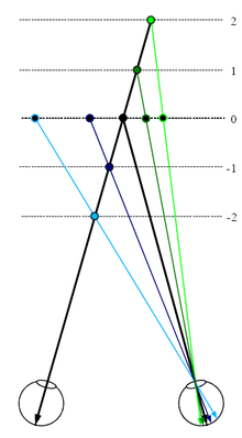
Figure 1: The full black circle is the point of fixation. The blue object lies nearer to the observer. Therefore, it has a "near" disparity dn. Objects lying more far away (green) correspondingly have a "far" disparity df. Binocular disparity is the angle between two lines of projection in one eye (mathematically, dn-df, with sign, measured counterclockwise). One of which is the real projection from the object to the actual point of projection. The other one is the imaginary projection running through the nodal point of the lens of the one eye to the point corresponding to the actual point of projection in the other eye. For simplicity reasons here both objects lie on the line of fixation for one eye such that the imaginary projection ends directly on the fovea of the other eye, but in general the fovea acts at most as a reference. Note that far disparities are smaller than near disparities for objects having the same distance from the fixation point.
In computer vision, binocular disparity is calculated from stereo images taken from a set of stereo cameras. The variable distance between these cameras, called the baseline, can affect the disparity of a specific point on their respective image plane. As the baseline increases, the disparity increases due to the greater angle needed to align the sight on the point. However, in computer vision, binocular disparity is referenced as coordinate differences of the point between the right and left images instead of a visual angle. The units are usually measured in pixels.
Tricking neurons with 2D images
Brain cells (neurons) in a part of the brain responsible for processing visual information coming from the retinae (primary visual cortex) can detect the existence of disparity in their input from the eyes. Specifically, these neurons will be active, if an object with "their" special disparity lies within the part of the visual field to which they have access (receptive field).[2]
Researchers investigating precise properties of these neurons with respect to disparity present visual stimuli with different disparities to the cells and look whether they are active or not. One possibility to present stimuli with different disparities is to place objects in varying depth in front of the eyes. However, the drawback to this method may not be precise enough for objects placed further away as they possess smaller disparities while objects closer will have greater disparities. Instead, neuroscientists use an alternate method as schematised in Figure 2.
Figure 2: The disparity of an object with different depth than the fixation point can alternatively be produced by presenting an image of the object to one eye and a laterally shifted version of the same image to the other eye. The full black circle is the point of fixation. Objects in varying depths are placed along the line of fixation of the left eye. The same disparity produced from a shift in depth of an object (filled coloured circles) can also be produced by laterally shifting the object in constant depth in the picture one eye sees (black circles with coloured margin). Note that for near disparities the lateral shift has to be larger to correspond to the same depth compared with far disparities. This is what neuroscientists usually do with random dot stimuli to study disparity selectivity of neurons since the lateral distance required to test disparities is less than the distances required using depth tests. This principle has also been applied in autostereogram illusions.
Computing disparity using digital stereo images
The disparity of features between two stereo images are usually computed as a shift to the left of an image feature when viewed in the right image.[3] For example, a single point that appears at the x coordinate t (measured in pixels) in the left image may be present at the x coordinate t - 3 in the right image. In this case, the disparity at that location in the right image would be 3 pixels.
Stereo images may not always be correctly aligned to allow for quick disparity calculation. For example, the set of cameras may be slightly rotated off level. Through a process known as image rectification, both images are rotated to allow for disparities in only the horizontal direction (i.e. there is no disparity in the y image coordinates).[3] This is a property that can also be achieved by precise alignment of the stereo cameras before image capture.
Computer algorithm
After rectification, the correspondence problem can be solved using an algorithm that scans both the left and right images for matching image features. A common approach to this problem is to form a smaller image patch around every pixel in the left image. These image patches are compared to all possible disparities in the right image by comparing their corresponding image patches. For example, for a disparity of 1, the patch in the left image would be compared to a similar-sized patch in the right, shifted to the left by one pixel. The comparison between these two patches can be made by attaining a computational measure from one of the following equations that compares each of the pixels in the patches. For all of the following equations, L and R refer to the left and right columns while r and c refer to the current row and column of either images being examined. "d" refers to the disparity of the right image.
- Normalized correlation:
- Sum of squared differences:
- Sum of absolute differences:


The disparity with the lowest computed value using one of the above methods is considered the disparity for the image feature. This lowest score indicates that the algorithm has found the best match of corresponding features in both images.
The method described above is a brute-force search algorithm. With large patch and/or image sizes, this technique can be very time consuming as pixels are constantly being re-examined to find the lowest correlation score. However, this technique also involves unnecessary repetition as many pixels overlap. A more efficient algorithm involves remembering all values from the previous pixel. An even more efficient algorithm involves remembering column sums from the previous row (in addition to remembering all values from the previous pixel). Techniques that save previous information can greatly increase the algorithmic efficiency of this image analyzing process.
Uses of disparity from images
Knowledge of disparity can be used in further extraction of information from stereo images. One case that disparity is most useful is for depth/distance calculation. Disparity and distance from the cameras are inversely related. As the distance from the cameras increases, the disparity decreases. This allows for depth perception in stereo images. Using geometry and algebra, the points that appear in the 2D stereo images can be mapped as coordinates in 3D space.
This concept is particularly useful for navigation. For example, the Mars Exploration Rover uses a similar method for scanning the terrain for obstacles.[4] The rover captures a pair of images with its stereoscopic navigation cameras and disparity calculations are performed in order to detect elevated objects (such as boulders).[5] Additionally, location and speed data can be extracted from subsequent stereo images by measuring the displacement of objects relative to the rover. In some cases, this is the best source of this type of information as the encoder sensors in the wheels may be inaccurate due to tire slippage.
In popular culture
Binocular disparity forms the premise for a sketch from the film Wayne's World in which Wayne, who is lying in bed as Tia Carrere's character, Cassandra, perches above him, compares the respective images from his left and right eyes while noting which is which by saying "Camera 1 ... Camera 2 ... Camera 1 ... Camera 2."
See also
References
- ↑ Qian, N., Binocular Disparity and the Perception of Depth, Neuron, 18, 359-368, 1997.
- ↑ Gonzalez, F. and Perez, R., Neural mechanisms underlying stereoscopic vision, Prog Neurobiol, 55(3), 191-224, 1998.
- 1 2 Linda G. Shapiro and George C. Stockman (2001). Computer Vision. Prentice Hall, 371-409. ISBN 0-13-030796-3.
- ↑ "The Computer Vision Laboratory ." JPL.NASA.GOV. JPL/NASA, n.d. Web. 5 Jun 2011. <https://www-robotics.jpl.nasa.gov/facilities/facilityImage.cfm?Facility=13&Image=335>.
- ↑ "Spacecraft: Surface Operations: Rover ." JPL.NASA.GOV. JPL/NASA, n.d. Web. 5 Jun 2011. http://marsrovers.jpl.nasa.gov/mission/spacecraft_rover_eyes.html.