Carnot heat engine

A Carnot heat engine[2] is an engine that operates on the reversible Carnot cycle. The basic model for this engine was developed by Nicolas Léonard Sadi Carnot in 1824. The Carnot engine model was graphically expanded upon by Benoît Paul Émile Clapeyron in 1834 and mathematically elaborated upon by Rudolf Clausius in 1857 from which the concept of entropy emerged.
Every thermodynamic system exists in a particular state. A thermodynamic cycle occurs when a system is taken through a series of different states, and finally returned to its initial state. In the process of going through this cycle, the system may perform work on its surroundings, thereby acting as a heat engine.
A heat engine acts by transferring energy from a warm region to a cool region of space and, in the process, converting some of that energy to mechanical work. The cycle may also be reversed. The system may be worked upon by an external force, and in the process, it can transfer thermal energy from a cooler system to a warmer one, thereby acting as a refrigerator or heat pump rather than a heat engine.
Carnot's diagram
In the adjacent diagram, from Carnot's 1824 work, Reflections on the Motive Power of Fire,[3] there are "two bodies A and B, kept each at a constant temperature, that of A being higher than that of B. These two bodies to which we can give, or from which we can remove the heat without causing their temperatures to vary, exercise the functions of two unlimited reservoirs of caloric. We will call the first the furnace and the second the refrigerator.”[4] Carnot then explains how we can obtain motive power, i.e., “work”, by carrying a certain quantity of heat from body A to body B.
Modern diagram
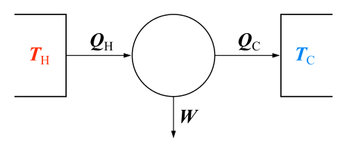
The previous image shows the original piston-and-cylinder diagram used by Carnot in discussing his ideal engines. The figure at right shows a block diagram of a generic heat engine, such as the Carnot engine. In the diagram, the “working body” (system), a term introduced by Clausius in 1850, can be any fluid or vapor body through which heat Q can be introduced or transmitted to produce work. Carnot had postulated that the fluid body could be any substance capable of expansion, such as vapor of water, vapor of alcohol, vapor of mercury, a permanent gas, or air, etc. Although, in these early years, engines came in a number of configurations, typically QH was supplied by a boiler, wherein water was boiled over a furnace; QC was typically supplied by a stream of cold flowing water in the form of a condenser located on a separate part of the engine. The output work W here is the movement of the piston as it is used to turn a crank-arm, which was then typically used to turn a pulley so to lift water out of flooded salt mines. Carnot defined work as “weight lifted through a height”.
Carnot cycle
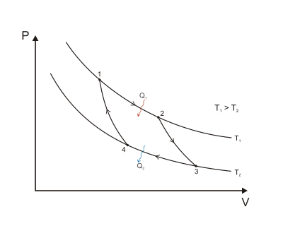
The Carnot cycle when acting as a heat engine consists of the following steps:
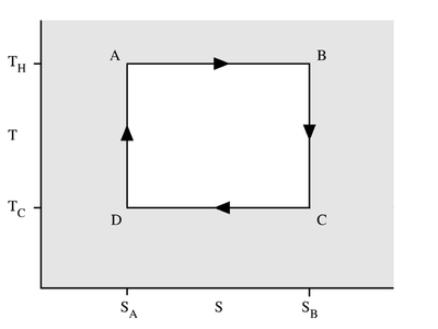
- Reversible isothermal expansion of the gas at the "hot" temperature, TH (isothermal heat addition or absorption). During this step (1 to 2 on Figure 1, A to B in Figure 2) the gas is allowed to expand and it does work on the surroundings. The temperature of the gas does not change during the process, and thus the expansion is isothermic. The gas expansion is propelled by absorption of heat energy Q1 and of entropy from the high temperature reservoir.
- Isentropic (reversible adiabatic) expansion of the gas (isentropic work output). For this step (2 to 3 on Figure 1, B to C in Figure 2) the piston and cylinder are assumed to be thermally insulated, thus they neither gain nor lose heat. The gas continues to expand, doing work on the surroundings, and losing an equivalent amount of internal energy. The gas expansion causes it to cool to the "cold" temperature, TC. The entropy remains unchanged.
- Reversible isothermal compression of the gas at the "cold" temperature, TC. (isothermal heat rejection) (3 to 4 on Figure 1, C to D on Figure 2) Now the surroundings do work on the gas, causing an amount of heat energy Q2 and of entropy to flow out of the gas to the low temperature reservoir. (This is the same amount of entropy absorbed in step 1.)
- Isentropic compression of the gas (isentropic work input). (4 to 1 on Figure 1, D to A on Figure 2) Once again the piston and cylinder are assumed to be thermally insulated. During this step, the surroundings do work on the gas, increasing its internal energy and compressing it, causing the temperature to rise to TH. The entropy remains unchanged. At this point the gas is in the same state as at the start of step 1.


Carnot's theorem

Carnot's theorem is a formal statement of this fact: No engine operating between two heat reservoirs can be more efficient than a Carnot engine operating between the same reservoirs.

Explanation
This maximum efficiency is defined as above:

- is the work done by the system (energy exiting the system as work),
- is the heat put into the system (heat energy entering the system),
- is the absolute temperature of the cold reservoir, and
- is the absolute temperature of the hot reservoir.


A corollary to Carnot's theorem states that: All reversible engines operating between the same heat reservoirs are equally efficient.
It is easily shown that the efficiency is maximum when the entire cyclic process is a reversible process. This means the total entropy of the total system consisting of the three parts: the entropy of the hot furnace, the entropy of the "working fluid" of the Heat engine, and the entropy of the cold sink. The total entropy of the system remains constant when the "working fluid" completes one cycle and returns to its original state. (In the general case, the total entropy of this combined system would increase in a general irreversible process).

Since the "working fluid" comes back to the same state after one cycle, and entropy of the system is a state function; the change in entropy of the "working fluid" system is 0. Thus, it implies that the total entropy change of the furnace and sink is zero, for the process to be reversible and the efficiency of the engine to be maximum. This derivation is carried out in the next section.
The Coefficient of Performance (COP) of the heat engine is the reciprocal of its efficiency.
Efficiency of real heat engines
For a real heat engine, the total thermodynamic process is generally irreversible. The working fluid is brought back to its initial state after one cycle, and thus the change of entropy of the fluid system is 0, but the sum of the entropy changes in the hot and cold reservoir in this one cyclical process is greater than 0.
The internal energy of the fluid is also a state variable, so its total change in one cycle is 0. So the total work done by the system , is equal to the heat put into the system minus the heat taken out .


For real engines, sections 1 and 3 of the Carnot Cycle; in which heat is absorbed by the "working fluid" from the hot reservoir, and released by it to the cold reservoir, respectively; no longer remain ideally reversible, and there is a temperature differential between the temperature of the reservoir and the temperature of the fluid while heat exchange takes place.
During heat transfer from the hot reservoir at to the fluid, the fluid would have a slightly lower temperature than , and the process for the fluid may not necessarily remain isothermal. Let be the total entropy change of the fluid in the process of intake of heat.


where the temperature of the fluid is always slightly lesser than , in this process.

So, one would get

Similarly, at the time of heat injection from the fluid to the cold reservoir one would have, for the magnitude of total entropy change of the fluid in the process of expelling heat:

- ,

where, during this process of transfer of heat to the cold reservoir, the temperature of the fluid is always slightly greater than .
We have only considered the magnitude of the entropy change here. Since the total change of entropy of the fluid system for the cyclic process is 0, we must have

The previous three equations combine to give:

Equations (2) and (7) combine to give

Hence,

where is the efficiency of the real engine, and is the efficiency of the Carnot engine working between the same two reservoirs at the temperatures and . For the Carnot engine, the entire process is 'reversible', and Equation (7) is an equality.

Hence, the efficiency of the real engine is always less than the ideal Carnot engine.
Equation (7) signifies that the total entropy of the total system(the two reservoirs + fluid) increases for the real engine, because the entropy gain of the cold reservoir as flows into it at the fixed temperature , is greater than the entropy loss of the hot reservoir as leaves it at its fixed temperature . The inequality in Equation (7) is essentially the statement of the Clausius theorem.
According to the second theorem, "The efficiency of the Carnot engine is independent of the nature of the working substance".
Notes
- ↑ Figure 1 in Carnot (1824, p. 17) and Carnot (1890, p. 63). In the diagram, the diameter of the vessel is large enough to bridge the space between the two bodies, but in the model, the vessel is never in contact with both bodies simultaneously. Also, the diagram shows an unlabeled axial rod attached to the outside of the piston.
- ↑ In French, Carnot uses machine à feu, which Thurston translates as heat-engine or steam-engine. In a footnote, Carnot distinguishes the steam-engine (machine à vapeur) from the heat-engine in general. (Carnot, 1824, p. 5 and Carnot, 1890, p. 43)
- ↑ Sometimes translated as Reflections on the Motive Power of Heat
- ↑ English translation by Thurston (Carnot, 1890, p. 51-52).
See also
References
- Carnot, Sadi (1824). Réflexions sur la puissance motrice du feu et sur les machines propres à développer cette puissance (in French). Paris: Bachelier. (First Edition 1824) and (Reissue of 1878)
- Carnot, Sadi (1890). Thurston, Robert Henry, ed. Reflections on the Motive Power of Heat and on Machines Fitted to Develop That Power. New York: J. Wiley & Sons. (full text of 1897 ed.) (Archived html version)