Circumferentor

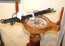
A circumferentor, or surveyor's compass, is an instrument used in surveying to measure horizontal angles. It was superseded by the theodolite in the early 19th century.[1]
A circumferentor consists of a circular brass box containing a magnetic needle, which moves freely over a brass circle, or compass divided into 360 degrees.[1][2] The needle is protected by a glass covering. [2] A pair of sights is located on the North-South axis of the compass.[1] Circumferentors were typically mounted on tripods and rotated on ball-and-socket joints.[2]
Circumferentors were made throughout Europe, including in England, France, Italy, and Holland. By the early 19th century, Europeans preferred theodolites to circumferentors. However, the circumferentor remained in common use in mines and in wooded or uncleared areas, such as in America.[1][2]
Usage

Measuring angles
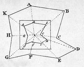
To measure an angle with a circumferentor, such as angle EKG (Figure 1), place the instrument at K, with the fleur-de-lis in the card towards you. Then direct the sights, until through them you see E; and note the degree pointed at by the south end of the needle, such as 296°. Then, turn the instrument around, with the fleur-de-lis still towards you, and direct the sights to G; note the degree at which the south end of the needle point, such as 182°. Finally, subtract the lesser number, 182, from the greater, 296°; the remainder, 114°, is the number of degrees in the angle EKG.
If the remainder is more than 180 degrees, it must be subtracted from 360 degrees.
Surveying a region
To take the plot of a field, forest, park, etc., with a circumferentor, consider region ABCDEFGHK in Figure 2, an area to be surveyed.
- Placing the instrument at A, the fleur-de-lis towards you, direct the sights to B; where suppose the south end of the needle cuts 191°; and the ditch, wall, or hedge, measuring with a Gunter's chain, contains 10 chains, 75 links.
- Placing the instrument at B, direct the sights as before to C; the south end of the needle, e.g. will cut 279°; and the line BC contains 6 chains and 83 links.
Then move the instrument to C; turn the sights to measure D, and measure CD as before. In the same manner, proceed to D, E, F, G, H, and lastly to K; still noting the degrees of every bearing, or angle, and the distances of every side. This will result in a table of the following form:
| Station | Degrees | Min. | Chains | Link |
|---|---|---|---|---|
| A | 191 | 00 | 10 | 75 |
| B | 297 | 00 | 6 | 83 |
| C | 216 | 30 | 7 | 82 |
| etc. | ||||
From this table, the field is to be plotted, or protracted.
Alternative plotting method:
An alternative way to plot the area in Figure 2 is to use several angles and only a few measurements and calculate their positions.
This could be done by starting at the center point in Figure 2 which is not labeled, but which will be referred to as "Center." Assume each point can be seen from each other point. From the "center" point, sight and record the angle to each point using the sights as described above. Then move to, and measure the distance to, one of the other points referenced, such as point B. At point B, measure the angles to all the other points. Then, move to an additional point such as point F. Again, measure the distance from the center to the point chosen (F). At that point, measure and record the angles to each of the other points as was done at point B. Chose a scale (a ratio between the size of the area to be plotted and the size of the paper on which you will draw the plot) that will allow the plot to fit on your paper and plot the angles and distances.
The advantage of this method over the first one above is that there are fewer distance measurements and any errors in angles or distances will not be cumulative; that is, if you use the first survey method, any angle that is slightly off will distort the remainder of the plot. The second method can also be used when it is not possible to measure some of the distances, for example, if there is a water barrier between two of the points. Also, if there are any inaccuracies in the measurements, they will be revealed in the plot because the points plotted from various angles will not coincide.
Additional considerations include the number of times the circumferentor must be set up and aligned. With the first method, the instrument must be set up at each point with a compass. With the second method, the initial set up is at "center." After that, for example at point B, the instrument can be set up by aligning the sight with the reciprocal of the angle between "center" and B. Thus, any local change in the magnetic field that would affect the compass would be nullified.
Surveyor's double prism
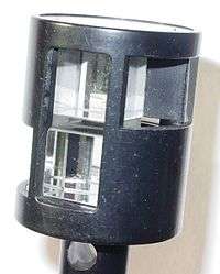
A double prism is a device to measure right angles, consisting of two five sided prisms stacked on top of each other and a plumb-bob. It is used to stake out right angles, for example on a construction site.
See also
References
- 1 2 3 4 Turner (1998). Scientific Instruments, 1500-1900: An Introduction. University of California Press. p. 43. ISBN 978-0-520-21728-7. Retrieved 3 July 2014.
- 1 2 3 4 Nesbit, Anthony; Baker, Thomas (1855). A complete Treatise on practical Land-Surveying, etc. With an engraved "Field-Book," being the notes on an estate in the Parish of Preston. pp. 343–344. Retrieved 3 July 2014.
 This article incorporates text from a publication now in the public domain: Chambers, Ephraim, ed. (1728). "article name needed". Cyclopædia, or an Universal Dictionary of Arts and Sciences (first ed.). James and John Knapton, et al.
- "Circumferentor". Oxford English Dictionary. Oxford University Press. 2nd edition. 1989.