Common emitter
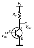
In electronics, a common emitter amplifier is one of three basic single-stage bipolar-junction-transistor (BJT) amplifier topologies, typically used as a voltage amplifier.
In this circuit the base terminal of the transistor serves as the input, the collector is the output, and the emitter is common to both (for example, it may be tied to ground reference or a power supply rail), hence its name. The analogous FET field-effect transistor circuit is the common source amplifier, and the analogous tube circuit is the common cathode amplifier.
Voltage gain of an amplifier is defined by
Vg=Vout/Vin
Emitter degeneration

Common emitter amplifiers give the amplifier an inverted output and can have a very high gain that may vary widely from one transistor to the next. The gain is a strong function of both temperature and bias current, and so the actual gain is somewhat unpredictable. Stability is another problem associated with such high gain circuits due to any unintentional positive feedback that may be present.
Other problems associated with the circuit are the low input dynamic range imposed by the small-signal limit; there is high distortion if this limit is exceeded and the transistor ceases to behave like its small-signal model. One common way of alleviating these issues is with emitter degeneration. This refers to the addition of a small resistor (or any impedance) between the emitter and the common signal source (e.g., the ground reference or a power supply rail). This impedance reduces the overall transconductance of the circuit by a factor of , which makes the voltage gain:


The voltage gain depends almost exclusively on the ratio of the resistors rather than the transistor's intrinsic and unpredictable characteristics. The distortion and stability characteristics of the circuit are thus improved at the expense of a reduction in gain.

(While this is often described as "negative feedback", as it reduces gain, raises input impedance, and reduces distortion, it predates the invention of negative feedback and does not reduce output impedance or increase bandwidth, as true negative feedback would do.)[1]
Characteristics
At low frequencies and using a simplified hybrid-pi model, the following small-signal characteristics can be derived.
| Definition | Expression (with emitter degeneration) | Expression (without emitter degeneration, i.e., RE = 0) | |
|---|---|---|---|
| Current gain | |||
| Voltage gain | |||
| Input impedance | |||
| Output impedance |


If the emitter degeneration resistor is not present, then , and the expressions effectively simplify to the ones given by the rightmost column (note that the voltage gain is an ideal value; the actual gain is somewhat unpredictable). As expected, when is increased, the input impedance is increased and the voltage gain is reduced.


Bandwidth
The bandwidth of the common-emitter amplifier tends to be low due to high capacitance resulting from the Miller effect. The parasitic base-collector capacitance appears like a larger parasitic capacitor (where is negative) from the base to ground.[2] This large capacitor greatly decreases the bandwidth of the amplifier as it makes the time constant of the parasitic input RC filter where is the output impedance of the signal source connected to the ideal base.


The problem can be mitigated in several ways, including:
- Reduction of the voltage gain magnitude (e.g., by using emitter degeneration).
- Reduction of the output impedance of the signal source connected to the base (e.g., by using an emitter follower or some other voltage follower).
- Using a cascode configuration, which inserts a low input impedance current buffer (e.g. a common base amplifier) between the transistor's collector and the load. This configuration holds the transistor's collector voltage roughly constant, thus making the base to collector gain zero and hence (ideally) removing the Miller effect.
- Using a differential amplifier topology like an emitter follower driving a grounded-base amplifier; as long as the emitter follower is truly a common-collector amplifier, the Miller effect is removed.

The Miller effect negatively affects the performance of the common source amplifier in the same way (and has similar solutions).When an AC signal is applied to the transistor amplifier it causes the base voltage VB to fluctuate in value at the AC signal. The positive half of the applied signal will cause an increase in the value of VB this turn will increase the base current IB and cause a corresponding increase in emitter current IE and collector current IC. As a result, the collector emitter voltage will be reduced because of the increase voltage drop across RL. The negative alternation of an AC signal will cause a decrease in IB this action then causes a corresponding decrease in IE through RL. The output signal of a common- emitter amplifier is therefore 180 degrees out of phase with the input signal.
It is also named common- emitter amplifier because the emitter of the transistor is common to both the input circuit and output circuit. The input signal is applied across the ground and the base circuit of the transistor. The output signal appears across ground and the collector of the transistor. Since the emitter is connected to the ground, it is common to signals, input and output.
The common- emitter circuit is the most widely used of junction, transistor amplifiers. As compared with the common- base connection, it has higher input impedance and lower output impedance. A single power supply is easily used for biasing. In addition, higher voltage and power gains are usually obtained for common- emitter (CE) operation.
Current gain in the common emitter circuit is obtained from the base and the collector circuit currents. Because a very small change in base current produces a large change in collector current, the current gain (β) is always greater than unity for the common-emitter circuit, a typical value is about 50.
Applications
Low frequency voltage amplifier
A typical example of the use of a common-emitter amplifier is shown in Figure 3.
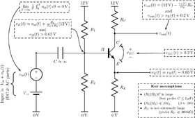
The input capacitor C removes any constant component of the input, and the resistors R1 and R2 bias the transistor so that it will remain in active mode for the entire range of the input. The output is an inverted copy of the AC-component of the input that has been amplified by the ratio RC/RE and shifted by an amount determined by all four resistors. Because RC is often large, the output impedance of this circuit can be prohibitively high. To alleviate this problem, RC is kept as low as possible and the amplifier is followed by a voltage buffer like an emitter follower.
Radio
Common-emitter amplifiers are also used in radio frequency circuits, for example to amplify faint signals received by an antenna. In this case it is common to replace the load resistor with a tuned circuit. This may be done to limit the bandwidth to a narrow band centered around the intended operating frequency. More importantly it also allows the circuit to operate at higher frequencies as the tuned circuit can be used to resonate any inter-electrode and stray capacitances, which normally limit the frequency response. Common emitters are also commonly used as low-noise amplifiers.
See also
References
- ↑ "Distortion and Feedback". sound.westhost.com. Retrieved 2016-01-27.
- ↑ Paul Horowitz and Winfield Hill (1989). The Art of Electronics (2nd ed.). Cambridge University Press. pp. 102–104. ISBN 978-0-521-37095-0.
External links
- Simulation of The Common Emitter Amplifier Circuit or simulation of Common Emitter Transistor Amplifier
- Basic BJT Amplifier Configurations
- NPN Common Emitter Amplifier – HyperPhysics
- ECE 327: Transistor Basics – Gives example common-emitter circuit with explanation.
 | Bipolar junction transistor: | .svg.png) | |
|---|---|---|---|
| Field-effect transistor: | |||
| Multiple transistors: | |||