Control moment gyroscope
A control moment gyroscope (CMG) is an attitude control device generally used in spacecraft attitude control systems. A CMG consists of a spinning rotor and one or more motorized gimbals that tilt the rotor’s angular momentum. As the rotor tilts, the changing angular momentum causes a gyroscopic torque that rotates the spacecraft.
Mechanics
CMGs differ from reaction wheels. The latter apply torque simply by changing rotor spin speed, but the former tilt the rotor's spin axis without necessarily changing its spin speed. CMGs are also far more power efficient. For a few hundred watts and about 100 kg of mass, large CMGs have produced thousands of newton meters of torque. A reaction wheel of similar capability would require megawatts of power.[1]
Design varieties
Single-gimbal
The most effective CMGs include only a single gimbal. When the gimbal of such a CMG rotates, the change in direction of the rotor's angular momentum represents a torque that reacts onto the body to which the CMG is mounted, e.g. a spacecraft. Except for effects due to the motion of the spacecraft, this torque is due to a constraint, so it does no mechanical work (i.e., requires no energy). Single-gimbal CMGs exchange angular momentum in a way that requires very little power, with the result that they can apply very large torques for minimal electrical input.
Dual-gimbal
Such a CMG includes two gimbals per rotor. As an actuator, it is more versatile than a single-gimbal CMG because it is capable of pointing the rotor's momentum vector in any direction. However, the torque generated by one gimbal's motion must often be reacted by the other gimbal on its way to the spacecraft, requiring more power for a given torque than a single-gimbal CMG. If the goal is simply to store momentum in a mass-efficient way, as in the case of the International Space Station, dual-gimbal CMGs are a good design choice. However, if a spacecraft instead requires large output torque while consuming minimal power, single-gimbal CMGs are a better choice.
Variable-speed
Most CMGs hold the rotor speed constant. Some academic research has focused on the possibility of spinning the rotor up and down as the CMG gimbals. These so-called variable-speed CMGs (VSCMGs) offer few practical advantages, mostly because the output torque from the rotor is likely orders of magnitude smaller than that caused by the gimbal motion. So, this effect adds nothing of practical value on the time scale of the motion typical of CMGs. However, thanks to the additional degree of freedom, the variable-speed CMG can be used to avoid the geometric singularity that is the most serious drawback of the conventional CMG. The VSCMG also can be used as a mechanical battery to store electric energy as kinetic energy of the flywheels.
Potential problems
Singularities
At least three single-axis CMGs are necessary for control of spacecraft attitude. However, no matter how many CMGs a spacecraft uses, gimbal motion can lead to relative orientations that produce no usable output torque along certain directions. These orientations are known as "singularities" and are related to the kinematics of robotic systems that encounter limits on the end-effector velocities due to certain joint alignments. Avoiding these singularities is naturally of great interest, and several techniques have been proposed. David Bailey and others have argued (in patents and in academic publications) that merely avoiding the "divide by zero" error that is associated with these singularities is sufficient.[2][3] Two more recent patents summarize competing approaches.[4][5] See also: Gimbal Lock.
Saturation
A cluster of CMGs can become saturated, in the sense that it is holding a maximum amount of angular momentum in a particular direction and can hold no more.
As an example, suppose a spacecraft equipped with two or more dual-gimbal CMGs experiences a transient unwanted torque, perhaps caused by reaction from venting waste gas, tending to make it roll clockwise about its forward axis and thus increase its angular momentum along that axis. Then the CMG control program will command the gimbal motors of the CMGs to slant the rotors' spin axes gradually more and more forward, so that the angular momentum vectors of the rotors point more nearly along the forward axis. While this gradual change in rotor spin direction is in progress, the rotors will be creating gyroscopic torques whose resultant is anticlockwise about the forward axis, holding the spacecraft steady against the unwanted waste gas torque.
When the transient torque ends, the control program will stop the gimbal movement, and the rotors will be left pointing more forward than before. The inflow of unwanted forward angular momentum has been routed through the CMGs and dumped into the rotors; the forward component of their total angular momentum vector is now greater than before.
If these events are repeated, the angular momentum vectors of the individual rotors will bunch more and more closely together round the forward direction. In the limiting case, they will all end up parallel, and the CMG cluster will now be saturated in that direction; it can hold no more angular momentum. If the CMGs were initially holding no angular momentum about any other axes, they will end up saturated exactly along the forward axis. If however (for example) they were already holding a little angular momentum in the "up" (yaw left) direction, they will saturate (end up parallel) along an axis pointing forward and slightly up, and so on. Saturation is possible about any axis.
In the saturated condition attitude control is impossible. Since the gyroscopic torques can now only be created at right angles to the saturation axis, roll control about that axis itself is now non-existent. There will also be major difficulties with control about other axes. For example, an unwanted left yaw can only be countered by storing some "up" angular momentum in the CMG rotors. This can only be done by tilting at least one of their axes up, which will slightly reduce the forward component of their total angular momentum. Since they can now store less "right roll" forward angular momentum, they will have to release some back into the spacecraft, which will be forced to start an unwanted roll to the right.[lower-alpha 1]
The only remedy for this loss of control is to desaturate the CMGs by removing the excess angular momentum from the spacecraft. The simplest way of doing this is to use Reaction Control System (RCS) thrusters. In our example of saturation along the forward axis, the RCS will be fired to produce an anticlockwise torque about that axis. The CMG control program will then command the rotor spin axes to begin fanning out away from the forward direction, producing gyroscopic torques whose resultant is clockwise about the forward direction, opposing the RCS as long as it is still firing and holding the spacecraft steady. This is continued until a suitable amount of forward angular momentum has been drained out of the CMG rotors; it is transformed into the moment of momentum of the moving matter in the RCS thruster exhausts and carried away from the spacecraft.[lower-alpha 2]
It is worth noting that "saturation" can only apply to a cluster of two or more CMGs, since it means that their rotor spins have become parallel. It is meaningless to say that a single constant-speed CMG can become saturated; in a sense it is "permanently saturated" in whatever direction the rotor happens to be pointing. This contrasts with a single reaction wheel, which can absorb more and more angular momentum along its fixed axis by spinning faster, until it reaches saturation at its maximum design speed.
Anti-parallel alignment
There are other undesirable rotor axis configurations apart from saturation, notably anti-parallel alignments. For example, if a spacecraft with two dual-gimbal CMGs gets into a state in which one rotor spin axis is facing directly forward, while the other rotor spin is facing directly aft (i.e. anti-parallel to the first), then all roll control will be lost. This happens for the same reason as for saturation; the rotors can only produce gyroscopic torques at right angles to their spin axes, and here these torques will have no fore-and-aft components and so no influence on roll. However in this case the CMGs are not saturated at all; their angular momenta are equal and opposite, so the total stored angular momentum adds up to zero. Just as for saturation, however, and for exactly the same reasons, roll control will become increasingly difficult if the CMGs even approach anti-parallel alignment.
In the anti-parallel configuration, although roll control is lost, control about other axes still works well (in contrast to the situation with saturation). An unwanted left yaw can be dealt with by storing some "up" angular momentum, which is easily done by tilting both rotor spin axes slightly up by equal amounts. Since their fore and aft components will still be equal and opposite, there is no change in fore-and-aft angular momentum (it will still be zero) and therefore no unwanted roll. In fact the situation will be improved, because the rotor axes are no longer quite anti-parallel and some roll control will be restored.
Anti-parallel alignment is therefore not quite as serious as saturation but must still be avoided. It is theoretically possible with any number of CMGs; as long as some rotors are aligned parallel along a particular axis, and all the others point in exactly the opposite direction, there is no saturation but still no roll control about that axis. With three or more CMGs the situation can be immediately rectified simply by redistributing the existing total angular momentum among the rotors (even if that total is zero).[lower-alpha 3] In practice the CMG control program will continually redistribute the total angular momentum to avoid the situation arising in the first place.
If there are only two CMGs in the cluster, as in our first example, then anti-parallel alignment will inevitably occur if the total stored angular momentum reaches zero. The remedy is to keep it away from zero, possibly by using RCS firings. This is not very satisfactory, and in practice all spacecraft using CMGs are fitted with at least three. However it sometimes happens that after malfunctions a cluster is left with only two working CMGs, and the control program must be able to deal with this situation.
Hitting the gimbal stops
Older CMG models like the ones launched with Skylab in 1973 had limited gimbal travel between fixed mechanical stops. On the Skylab CMGs the limits were plus or minus 80 degrees from zero for the inner gimbals, and from plus 220 degrees to minus 130 degrees for the outer ones (so zero was offset by 45 degrees from the centre of travel). Visualising the inner angle as 'latitude' and the outer as 'longitude', it can be seen that for an individual CMG there were 'blind spots' with radius 10 degrees of latitude at the 'North and South poles', and an additional 'blind strip' of width 10 degrees of 'longitude' running from pole to pole, centred on the line of 'longitude' at plus 135 degrees. These 'blind areas' represented directions in which the rotor's spin axis could never be pointed.[6]:11
Skylab carried three CMGs, mounted with their casings (and therefore their rotor axes when the gimbals were set to zero) facing in three mutually perpendicular directions. This ensured that the six 'polar blind spots' were spaced 90 degrees apart from each other. The 45 degree zero offset then ensured that the three 'blind strips' of the outer gimbals would pass halfway between neighbouring 'polar blind spots' and at a maximum distance from each other. The whole arrangement ensured that the 'blind areas' of the three CMGs never overlapped, and thus that at least two of the three rotor spins could be pointed in any given direction.[6]:4
The CMG control program was responsible for making sure that the gimbals never hit the stops, by redistributing angular momentum between the three rotors to bring large gimbal angles closer to zero. Since the total angular momentum to be stored had only three degrees of freedom, while the control program could change six independent variables (the three pairs of gimbal angles), the program had sufficient freedom of action to do this while still obeying other constraints such as avoiding anti-parallel alignments.[6]:5
One advantage of limited gimbal movement such as Skylab's is that singularities are less of a problem. If Skylab's inner gimbals had been able to reach 90 degrees or more away from zero, then the 'North and South poles' could have become singularities; the gimbal stops prevented this.
More modern CMGs such as the four units installed on the ISS in 2000 have unlimited gimbal travel and therefore no 'blind areas'. Thus they do not have to be mounted facing along mutually perpendicular directions; the four units on the ISS all face the same way. The control program need not concern itself with gimbal stops, but on the other hand it must pay more attention to avoiding singularities.
Applications
Skylab
Skylab, launched in May 1973, was the first spacecraft to be fitted with large CMGs for attitude control. [7] Three dual-gimbal CMGs were mounted on the equipment rack of the Apollo Telescope Mount at the hub of the windmill-shaped array of solar panels on the side of the station. They were arranged so that the casings (and therefore the rotors when all gimbals were at their zero positions) pointed in three mutually perpendicular directions. Since the units were dual-gimballed, each one could produce a torque about any axis at right angles to its rotor axis, thus providing some redundancy; if any one of the three failed, the combination of the remaining two could in general still produce a torque around any desired axis.[6]
Gyrodynes on Salyut and Mir
CMGs were used for attitude control on the Salyut and Mir space stations, where they were called gyrodynes (from the Russian гиродин girodin; this word is also sometimes used – especially by Russian crew – for the CMGs on the ISS).[8] They were first tested on Salyut 3 in 1974, and introduced as standard components from Salyut 6 onwards.[9] The completed Mir station had twelve gyrodynes altogether, starting with six in the pressurised interior of the Kvant-1 module.[10] These were later supplemented by another six on the unpressurised outside of Kvant-2. According to NPO Energia, putting them outside turned out to be a mistake, as it made gyrodyne replacement much more difficult.[11]
International Space Station
The ISS employs a total of four CMGs as primary actuating devices during normal flight mode operation. The objective of the CMG flight control system is to hold the space station at a fixed attitude relative to the surface of the Earth. In addition, it seeks a Torque Equilibrium Attitude (TEA), in which the combined torque contribution of gravity gradient, atmospheric drag, solar pressure, and geomagnetic interactions are minimized. In the presence of these continual environmental disturbances CMGs absorb momentum in an attempt to maintain the space station at a desired attitude. The CMGs will eventually saturate (absorbing momentum to the point where they can absorb no more), resulting in loss of effectiveness of the CMG array for control. Some kind of momentum management scheme (MMS) is necessary to allow the CMGs to hold a desired attitude and at the same time prevent CMG saturation. Since the CMGs are momentum-exchange devices, external control torques must be used to desaturate the CMGs, that is, bring the momentum back to nominal value. Some methods for unloading CMG momentum include the use of magnetic torques, reaction thrusters, and gravity gradient torque. For the space station, the gravity gradient torque approach is preferred because it requires no consumables or external hardware and because the gravity-gradient torque on the ISS can be very high.[12]
Proposed
As of 2016, the Russian Orbital Segment of the ISS carries no CMGs of its own. However, the proposed but as yet unbuilt Science and Power Module (NEM-1) would be fitted with several externally-mounted CMGs.[13] NEM-1 would be installed on one of the lateral ports of the small UM or Nodal Module scheduled for completion and launch at some time within the 2016–25 Russian programme. Its twin NEM-2 (if completed) would later be installed symmetrically on the other lateral UM port.
On 24 February 2015, the Scientific and Technical Council of Roscosmos announced that after decommissioning of the ISS (then planned for 2024) the newer Russian modules would be detached and form the nucleus of a small all-Russian space station to be called OPSEK.[14][15] If this plan is carried out, the CMGs on NEM-1 (and NEM-2, if built) would provide attitude control for the new Russian station.
-
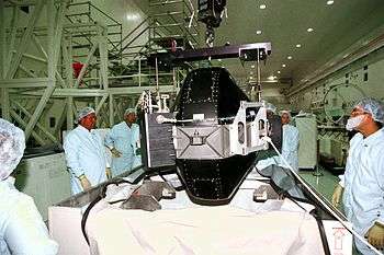
Control Moment Gyroscope (CMG)
-

CMG drawing (cover removed)
See also
Notes
- ↑ In fact control will already be difficult even when the cluster is not quite saturated. For example, roll control needs the gyroscopic torques to have a forward-facing component. Those gyroscopic torques are always at right angles to the rotor spin axes, so near saturation in our example the forward-facing components are quite small compared to the total gyroscopic torques. This means that the total gyroscopic torques will have to be quite large to give usable roll control, and this can only be achieved by making the gimbal motions faster. Eventually these will exceed the capabilities of the gimbal motors.
- ↑ It might be asked why the RCS thrusters were not used originally to directly oppose the torque created by the waste gas venting, thus bypassing the CMGs altogether and rendering them unnecessary. One answer is that RCS thrusters usually produce much more thrust than venting waste gas, or the other likely causes of unwanted torque; a few seconds of RCS firing can drain away angular momentum that has taken hours to accumulate in the CMGs. The RCS is used for "coarse" attitude control, with the CMGs providing "fine" adjustments. Another reason for temporarily storing angular momentum in the CMGs is that quite possibly one unwanted torque may be followed some time later by another unwanted torque in the opposite direction. In this case the angular momentum left stored after the first event is used to counter the second event, without expenditure of precious RCS fuel. Cyclic unwanted torques like this are often caused by orbital interactions with a gravity gradient.
- ↑ For example, suppose there are four CMGs and the starting configuration is two spins facing forward and two facing back. Then one of the forward-facing rotors can be swung smoothly to "up", while one rear-facing rotor is swung simultaneously to "down". The resulting gyroscopic torques will cancel each other out exactly while this motion is in progress, and the final "+" shaped configuration is no longer anti-parallel.
References
- ↑ "R Votel, D Sinclair. "Comparison of control moment gyros and reaction wheels for small Earth-observing satellites." 26th Annual AIAA/USU Conference on Small Satellites.".
- ↑ "Orienting a satellite with controlled momentum gyros - US Patent 6154691". Patft.uspto.gov. Retrieved 2013-10-03.
- ↑ Heiberg, Christopher J.; Bailey, David; Wie, Bong (January 2000). "Precision Spacecraft Pointing Using Single-Gimbal Control Moment Gyroscopes with Disturbance". Journal of Guidance, Control, and Dynamics. American Institute of Aeronautics and Astronautics. 23 (1): 77–85. doi:10.2514/2.4489. ISSN 0731-5090. Retrieved 31 March 2016.
- ↑ US Patent 7246776
- ↑ "US Patent Application 20070124032". Appft1.uspto.gov. Retrieved 2013-10-03.
- 1 2 3 4 Chubb, W. B.; Seltzer, S. M. (February 1971). "Skylab Attitude and Pointing Control System" (PDF). ntrs.nasa.gov. NASA Technical Notes. Retrieved 1 April 2016.
- ↑ Belew, Leland F. (1977). "SP-400 Skylab, Our First Space Station; Chapter 3: "We Can Fix Anything"". history.nasa.gov. NASA History Office. Retrieved 1 April 2016.
- ↑ Foale, Michael (19 June 1998). "Navigating on Mir". www.mathematica-journal.com. The Mathematica Journal. Retrieved 30 March 2016.
- ↑ Zak, Anatoly. "OPS-2 (Salyut-3)". www.russianspaceweb.com. Anatoly Zak. Retrieved 30 March 2016.
- ↑ Zak, Anatoly. "Kvant-1 Module". www.russianspaceweb.com. Anatoly Zak. Retrieved 30 March 2016.
- ↑ Zak, Anatoly. "Kvant-2 Module". www.russianspaceweb.com. Anatoly Zak. Retrieved 30 March 2016.
- ↑ A. Pothiawala, M.A. Dahleh, Hoo OPTIMAL CONTROL FOR THE ATTITUDE CONTROL AND MOMENTUM MANAGEMENT OF THE SPACE STATION, MIT, Cambridge, MA 02139, URL=http://dspace.mit.edu/bitstream/1721.1/3208/1/P-1985-22200134.pdf
- ↑ Zak, Anatoly. "Russia works on a new-generation station module". www.russianspaceweb.com. Anatoly Zak. Archived from the original on 8 April 2016. Retrieved 5 April 2016.
- ↑ Zak, Anatoly. "OPSEK Project". www.russianspaceweb.com. Anatoly Zak. Archived from the original on 22 March 2016. Retrieved 5 April 2016.
- ↑ Zak, Anatoly. "Uninternational space station". www.russianspaceweb.com. Anatoly Zak. Retrieved 5 April 2016.
External links
CMG applications and fundamental research are undertaken at several institutions.
- Georgia Tech's Panagiotis Tsiotras has studied variable-speed CMGs in connection with flywheel energy storage and has built a spacecraft simulator based on them: faculty page
- Virginia Tech's Christopher Hall has built a spacecraft simulator as well: faculty page
- Texas A&M's John Junkins and Srinivas Vadali have written papers on VSCMGs for use in singularity avoidance: faculty page
- Cornell's Mason Peck is researching CMG-driven nanosats with the Violet spacecraft: Violet project page
- Space Systems Group at the University of Florida under Prof. Norman Fitz-Coy have been researching on the development of CMGs for pico- and nano-satellites and on various steering logics for singularity avoidance SSG
- Professor Brij Agrawal at the Naval Postgraduate School has built two spacecraft simulators, at least one of which uses CMGs:
- Honeywell Defense and Space Systems performs research in [broken link] Control Moment Gyros They also have developed a spacecraft simulator driven by CMGs: [broken link] CMG Testbed Video
- Naval Postgraduate School's Marcello Romano has studied variable-speed CMGs and has developed a mini single gimbal control moment gyro for laboratory experiment of spacecraft proximity maneuvers faculty page