Crankcase ventilation system
A crankcase ventilation system is a one way passage for gases to escape in a controlled manner from the crankcase of an internal combustion engine.
This is necessary because internal combustion inevitably involves a small but continual amount of blow-by, which occurs when some of the gases from the combustion leak past the piston rings (that is, blow by them) to end up inside the crankcase, causing pressure to build up in the crank case. For control of the pressure inside it, a PCV (positive crankcase ventilation) valve is used to vent the crankcase.
Early provisions
From the late 19th century through the early 20th, blow-by gases from internal combustion were allowed to find their own way out to the atmosphere past seals and gaskets. It was considered normal for oil to be found both inside and outside an engine, and for oil to drip to the ground in small but constant amounts. The latter had also been true for steam engines and steam locomotives in the decades before. Even bearing and valve designs generally made little to no provision for keeping oil or waste gases contained. Sealed bearings and valve covers were for special applications only. Gaskets and shaft seals were meant to limit loss of oil, but they were usually not expected to entirely prevent it. On internal combustion engines, the hydrocarbon-rich blow-by gases would diffuse through the oil in the seals and gaskets into the atmosphere. Engines with high amounts of blow-by (e.g., worn out ones, or ones not well built to begin with) would leak profusely via those routes.
Road draft tube
The first refinement in crankcase ventilation was the road draft tube, which is a pipe running from a high location contiguous to the crankcase (such as the side of the engine block, or the valve cover on an overhead valve engine) down to an open end facing down and located in the vehicle's slipstream. When the vehicle is moving, airflow across the open end of the tube creates a draft that pulls gases out of the crankcase. The high location of the engine end of the pipe minimises liquid oil loss. An air inlet path to the crankcase, called the breather and often incorporated into the oil filler cap, meant that when a draft was generated at the tube, fresh air swept through the crankcase to clear out the blow-by gases.[1]
The road draft tube, though simple, has shortcomings: it does not function when the vehicle is moving too slowly to create a draft, so postal and other slow-moving delivery vehicles tended to suffer rapid buildup of engine sludge due to poor crankcase ventilation. And non-road vehicles such as boats never generated a draft on the tube, no matter how fast they were going.[1] The draft tube discharged the crankcase gases, composed largely of unburnt hydrocarbons, directly into the air. This created pollution as well as objectionable odors.[1] Moreover, the draft tube could become clogged with snow or ice, in which case crankcase pressure would build and cause oil leaks and gasket failure.[2]
Positive crankcase ventilation (PCV)
During World War II a different type of crankcase ventilation had to be invented to allow tank engines to operate during deep fording operations, where the normal draft tube ventilator would have allowed water to enter the crankcase and destroy the engine.[3] The PCV system and its control valve were invented to meet this need, but no need for it on automobiles was recognized.
In 1952, Professor A. J. Haagen-Smit, of the California Institute of Technology at Pasadena, postulated that unburned hydrocarbons were a primary constituent of smog, and that gasoline powered automobiles were a major source of those hydrocarbons. The GM Research Laboratory (led by Dr. Lloyd L. Withrow) discovered in 1958 that the road draft tube was a major source—about half—of the hydrocarbons coming from the automobile. The PCV system thus became the first real vehicle emissions control device.
Positive crankcase ventilation was first factory-installed on a widespread basis by law on all new 1961-model cars first sold in California. The following year, New York required it. By 1964, most new cars sold in the U.S. were so equipped by voluntary industry action so as not to have to make multiple state-specific versions of vehicles. PCV quickly became standard equipment on all vehicles worldwide because of its benefits not only in emissions reduction but also in engine internal cleanliness and oil lifespan.[1][4]
In 1967, several years after its introduction into production, the PCV system became the subject of a U.S. federal grand jury investigation, when it was alleged by some industry critics that the AMA was conspiring to keep several such smog reduction devices on the shelf to delay additional smog control. After eighteen months of investigation by U.S. Attorney Samuel Flatow, the grand jury returned a "no-bill" decision, clearing the AMA, but resulting in a consent decree that all U.S. automobile companies agreed not to work jointly on smog control activities for a period of ten years.
In the decades since, legislation and regulation of vehicular emissions has tightened substantially. Today's petrol engines continue to use PCV systems.
Components and details
Breather
In order for the PCV system to sweep fumes out of the crankcase, the crankcase must have a source of fresh, clean air, called the crankcase breather. To achieve this, the crankcase air inlet is usually ducted to the engine's air cleaner. The breather is usually provided with baffles and filters to prevent oil mist and vapour from fouling the air filter.
Intake manifold vacuum is applied to the crankcase via the PCV valve, drawing fresh air into the crankcase via the breather. The airflow through the crankcase and engine interior sweeps away combustion byproduct gases, including a large amount of water vapour which includes dissolved chemical combustion byproducts. This mixture of air and crankcase gases then exits, often via another simple baffle, screen, or mesh to exclude oil droplets, through the PCV valve and into the intake manifold. On some PCV systems, this oil baffling takes place in a discrete replaceable part called the 'oil separator'.
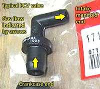
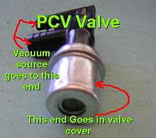
PCV valve or orifice
The PCV valve is a variable orifice that controls the flow of crankcase fumes, admixed with fresh air admitted to the crankcase by the breather, into the intake tract. With no manifold vacuum, a restrictor—generally a cone or ball—is held by a light spring in a position exposing the full size of the valve's orifice to the intake manifold. With the engine running, the restrictor is drawn towards the orifice by manifold vacuum, restricting the opening proportionate to the level of engine vacuum vs. spring tension. At idle, manifold vacuum is high, but a large amount of extra air would amount to a vacuum leak, causing the engine to run too lean and/or too fast. So at high manifold vacuum, the PCV valve allows only a low flow rate. This is in accordance with the low volume of crankcase fumes generated at low engine speeds. At higher engine speeds, with less manifold vacuum, the PCV valve permits a greater flow rate to keep up with the greater volume of crankcase fumes; because of the higher engine speed, a greater amount of "extra" air via the PCV system can be tolerated without upsetting the engine's running. At full throttle, very little manifold vacuum is present, so there is little flow through the PCV valve. However, this is the condition under which the maximum volume of crankcase gas is present. Most of it escapes under its own pressure via the crankcase breather, flowing into the engine's intake tract via the air cleaner.
A second function of the PCV valve is to protect the engine in case of a backfire, which causes a sudden high-pressure pulse in the intake manifold. This forces the PCV valve closed so that the backfire flame can't reach the crankcase, where it could ignite flammable fumes and cause damage. turbocharged engines also experience periods of high intake manifold pressure during which the PCV valve is closed and the crankcase fumes are admitted to the engine via the breather and air cleaner.
Some engines use a fixed orifice rather than a variable-orifice PCV valve.
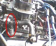
Component placement
The crankcase air outlet, where the PCV valve is located, is generally separated as widely as practical from the crankcase air inlet. For example, the inlet and outlet are frequently on opposite valve covers on a V engine, or on opposite ends of the one and only valve cover on an inline engine. The PCV valve is often, but not always, placed at the valve cover; it may be located anywhere between the crankcase air outlet and the intake manifold.
System function and maintenance
It is critical that the parts of the PCV system be kept clean and open, otherwise air flow will be insufficient. A plugged or malfunctioning PCV valve by itself cannot damage an engine; however the blowby will flow up in a reverse fashion up through the crankcase air inlet and if there isn't a separate catch can or oil separator at that inlet, then the blowby will contaminate the air intake manifold. On boosted engines this can be a real problem. A poorly maintained engine's PCV system will eventually contaminate the air intake manifold with oil sludge and if both the pcv valve and the crankcase air inlet are blocked then the crankcase pressure will build to a level that will damage seals and eventually the motor.
Alternatives
Not all petrol engines have PCV valves. Dragsters sometimes use a scavenger system and venturi tube in the exhaust to draw out combustion gases and maintain a small amount of vacuum in the crankcase to prevent oil leaks on to the race track. Small two stroke engines use the crankcase to partially compress incoming air; all crankcase gases are thus burned in the regular flow of air and fuel through the engine. Many small four-stroke engines such as lawn mower engines and small gasoline generators, simply use a draft tube connected to the intake, between the air filter and carburetor, to route all blow by back into the intake mixture. The higher operating temperature of these small engines prevents large amounts of water vapor and light hydrocarbons from condensing in the engine oil.
References
- 1 2 3 4 Rosen (Ed.), Erwin M. (1975). The Peterson automotive troubleshooting & repair manual. Grosset & Dunlap, Inc. ISBN 978-0-448-11946-5.
- ↑ Gus Saves a Friend from a Snow Job, Popular Science, February 1966
- ↑ TM 9-1756A, Ordnance Maintenance-Ordnance. Department of Defense. 1943. pp. RA PD 311003.
- ↑ NAPA Echlin Service Bulletin: Crankcase and Exhaust Emission Control; February 1968