Polarity (mutual inductance)
The Polarity or Dot Notation for a device with mutual inductance designates the relative instantaneous current directions of such device's winding leads.[1]
Physical Meaning of the Polarity or Dotted Notation
The physical criteria of this notation is to preserve a proper magnetic flow circuit direction inside the material. Keeping all current entering a transformer or coupled inductances, in phase, through dotted leads or ports will keep the magnetic flow circulating without cancelling each other, and the device will work under their rated efficiency.
Entering current on different dotted ports -one in a dotted port and the other with an un-dotted port- will cause the magnetic flow components to sustract each other, making the device working ineficciently. This criteria holds for devices with several coils, in order to have each of them aggregating in an aditive way by entering dotted ports.
Leads of primary and secondary windings are said be of the same polarity when instantaneous current entering the primary winding lead results in instantaneous current leaving the secondary winding lead as though the two leads were a continuous circuit.[1][2] In the case of two windings wound around the same core in parallel, for example, the polarity will be the same on the same ends: A sudden (instantaneous) current in the first coil will induce a voltage opposing the sudden increase (Lenz's law) in the first and also in the second coil, because the inductive magnetic field produced by the current in the first coil traverses the two coils in the same manner. The second coil will therefore show an induced current opposite in direction to the inducing current in the first coil. Both leads behave like a continuous circuit, one current entering into the first lead and another current leaving the second lead.
Marking Methods
A dot marking convention, or alphanumeric marking convention, or both, can be used to denote the same relative instantaneous polarity of two mutually inductive components such as between transformer windings. These markings may be found on transformer cases beside terminals, winding leads, nameplates, schematic and wiring diagrams.
Transformer windings
Two methods are commonly used to denote which terminals present the same relative polarity. A dot may be used, or an alphanumeric designation. Alphanumeric designations are typically in the form H1 for primaries, and for secondaries, X1, (and Y1, Z1, if more windings present).
Unlike single-phase transformers, three-phase transformers may incorporate a phase shift due to different winding configurations resulting in a multiple of 30 degree phase shift between H1 and X1 bushing designations.
Terminal layout conventions
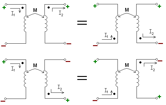
Referring to the circuit diagrams below: The circuit polarity signs '+' and '-' indicate the relative polarities of the induced voltages in both coils, i.e. how an instantaneous (sudden) magnetic field traversing the primary and secondary coils induces a voltage in both coils.
- The instantaneous polarities of the voltages across each inductor with respect to the dotted terminals are the same.[3]
- The circuit arrows indicate example applied and resultant relative current directions. The '+' and '-' polarities in the diagram are not the voltages driving the currents.
- The instantaneous directions of the current entering the primary inductor at its dotted end and the current leaving of the secondary inductor at its dotted end are the same.
- Subtractive polarity transformer designs are shown in the upper circuit diagrams. Additive polarity transformer designs are shown in the lower circuit diagrams.[4]
Autotransformers
If two mutually coupled inductors are in series, the dot convention can be used in the same manner as in the case of autotransformers. Relative polarity in autotransformer drawings is usually quite obvious by physical placement of the windings in circuit drawings.
See also
References
- 1 2 Knowlton & p.552, §15.
- ↑ Alexander 2009, p. 559–560.
- ↑ "PS-E-15 — Provisional Specifications for Approval of Electronic Voltage Transformers". Measurement Canada. Retrieved 18 April 2013.
- ↑ "Transformer Polarity" (PDF). .idc-online/electrical_engineering. Retrieved 23 April 2013.
Bibliography
- Alexander, Charles (2009). Fundamentals of electric circuits. McGraw-Hill. ISBN 0073529559.
- Grossner, Nathan (1967). Transformers for Electronic Circuits. McGraw-Hill. p. 26. ISBN 0070249792.
- ANSI/IEEE C57.13, American National Standard Requirements for Instrument Transformers
- Brenner, Egon; Javid, Mansour (1959). "§18.1 'Symbols and Polarity of Mutual Inductance' in Chapter 18 - Circuits with Magnetic Circuits". Analysis of Electric Circuits. McGraw-Hill. pp. 589–590.
- Boylestad, Robert L. (2003). "Section 21.8: Series connection of mutually coupled coils". Introductory Circuit Analysis (10th ed.). Prentice Hall. p. 954. ISBN 0-13-097417-X.
- Knowlton, A.E. (Ed.) (1949). Standard Handbook for Electrical Engineers (8th ed.). McGraw-Hill. p. 552, §6-15 & p. 606, §6-162.
- Kothari, D.P.; Nagrath, I.J. (2010). §3.7 'Transformer Testing' in Chapter 3 - Transformers (4th ed.). Tata McGraw-Hill. p. 73. ISBN 978-0-07-069967-0.
- Parker, M. R; Ula, S.; Webb, W. E. (2005). "§2.5.5 'Transformers' & §10.1.3 'The Ideal Transformer'". In Whitaker, Jerry C. The Electronics Handbook (2nd ed.). Taylor & Francis. pp. 172, 1017. ISBN 0-8493-1889-0.