Drill string
A drill string on a drilling rig is a column, or string, of drill pipe that transmits drilling fluid (via the mud pumps) and torque (via the kelly drive or top drive) to the drill bit. The term is loosely applied to the assembled collection of the drill pipe, drill collars, tools and drill bit. The drill string is hollow so that drilling fluid can be pumped down through it and circulated back up the annulus (the void between the drill string and the casing/open hole).
Drill string components
The drill string is typically made up of three sections:
- Bottom hole assembly (BHA)
- Transition pipe, which is often heavyweight drill pipe (HWDP)
- Drill pipe
Bottom hole assembly (BHA)
The BHA is made up of: a drill bit, which is used to break up the rock formations; drill collars, which are heavy, thick-walled tubes used to apply weight to the drill bit; and drilling stabilizers, which keep the assembly centered in the hole. The BHA may also contain other components such as a downhole motor and rotary steerable system, measurement while drilling (MWD), and logging while drilling (LWD) tools. The components are joined together using rugged threaded connections. Short "subs" are used to connect items with dissimilar threads.
Transition pipe
Heavyweight drill pipe (HWDP) may be used to make the transition between the drill collars and drill pipe. The function of the HWDP is to provide a flexible transition between the drill collars and the drill pipe. This helps to reduce the number of fatigue failures seen directly above the BHA. A secondary use of HWDP is to add additional weight to the drill bit. HWDP is most often used as weight on bit in deviated wells. The HWDP may be directly above the collars in the angled section of the well, or the HWDP may be found before the kick off point in a shallower section of the well.
Drill pipe
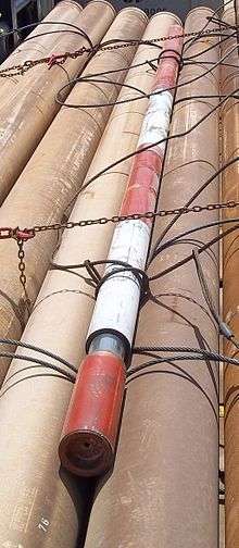
Drill pipe makes up the majority of the drill string back up to the surface. Each drill pipe comprises a long tubular section with a specified outside diameter (e.g. 3 1/2 inch, 4 inch, 5 inch, 5 1/2 inch, 5 7/8 inch, 6 5/8 inch). At each end of the drill pipe tubular, larger-diameter portions called the tool joints are located. One end of the drill pipe has a male ("pin") connection whilst the other has a female ("box") connection. The tool joint connections are threaded which allows for the make of each drill pipe segment to the next segment.
Running a drill string
Most components in a drill string are manufactured in 31 foot lengths (range 2) although they can also be manufactured in 46 foot lengths (range 3). Each 31 foot component is referred to as a joint. Typically 2, 3 or 4 joints are joined together to make a stand. Modern onshore rigs are capable of handling ~90 ft stands (often referred to as a triple).
Pulling the drill string out of or running the drill string into the hole is referred to as tripping. Drill pipe, HWDP and collars are typically racked back in stands in to the monkeyboard which is a component of the derrick if they are to be run back into the hole again after, say, changing the bit. The disconnect point ("break") is varied each subsequent round trip so that after three trips every connection has been broken apart and later made up again with fresh pipe dope applied.
Stuck drill string
A stuck drill string can be caused by many situations.
- Packing-off due to cuttings settling back into the wellbore when circulation is stopped.
- Differentially when there is a large difference between formation pressure and wellbore pressure. The drill string is pushed against one side of the well bore. The force required to pull the string along the wellbore in this occurrence is a function of the total contact surface area, the pressure difference and the friction factor.
- Keyhole sticking occurs mechanically as a result of pulling up into doglegs when tripping.
- Adhesion due to not moving it for a significant amount of time.
Once the tubular member is stuck, there are many techniques used to extract the pipe. The tools and expertise are normally supplied by an oilfield service company. Two popular tools and techniques are the oilfield jar and the surface resonant vibrator. Below is a history of these tools along with how they operate.
History of Jars
The mechanical success of cable tool drilling has greatly depended on a device called jars, invented by a spring pole driller, William Morris, in the salt well days of the 1830s. Little is known about Morris except for his invention and that he listed Kanawha County (now in West Virginia) as his address. Morris received US 2243 for this unique tool in 1841 for artesian well drilling. Later, using jars, the cable tool system was able to efficiently meet the demands of drilling wells for oil.
The jars were improved over time, especially at the hands of the oil drillers, and reached the most useful and workable design by the 1870s, due to another US 78958 received in 1868 by Edward Guillod of Titusville, Pennsylvania, which addressed the use of steel on the jars' surfaces that were subject to the greatest wear. Many years later, in the 1930s, very strong steel alloy jars were made.
A set of jars consisted of two interlocking links which could telescope. In 1880 they had a play of about 13 inches such that the upper link could be lifted 13 inches before the lower link was engaged. This engagement occurred when the cross-heads came together.Today, there are two primary types, hydraulic and mechanical jars. While their respective designs are quite different, their operation is similar. Energy is stored in the drillstring and suddenly released by the jar when it fires. Jars can be designed to strike up, down, or both. In the case of jarring up above a stuck bottomhole assembly, the driller slowly pulls up on the drillstring but the BHA does not move. Since the top of the drillstring is moving up, this means that the drillstring itself is stretching and storing energy. When the jars reach their firing point, they suddenly allow one section of the jar to move axially relative to a second, being pulled up rapidly in much the same way that one end of a stretched spring moves when released. After a few inches of movement, this moving section slams into a steel shoulder, imparting an impact load.
In addition to the mechanical and hydraulic versions, jars are classified as drilling jars or fishing jars. The operation of the two types is similar, and both deliver approximately the same impact blow, but the drilling jar is built such that it can better withstand the rotary and vibrational loading associated with drilling. Jars are designed to be reset by simple string manipulation and are capable of repeated operation or firing before being recovered from the well. Jarring effectiveness is determined by how rapidly you can impact weight into the jars. When jarring without a compounder or accelerator you rely only on pipe stretch to lift the drill collars upwards after the jar releases to create the upwards impact in the jar. This accelerated upward movement will often be reduced by the friction of the working string along the sides of the well bore, reducing the speed of upwards movement of the drill collars which impact into the jar. At shallow depths jar impact is not achieved because of lack of pipe stretch in the working string.
When pipe stretch alone cannot provide enough energy to free a fish, compounders or accelerators are used. Compounders or accelerators are energized when you over pull on the working string and compress a compressible fluid through a few feet of stroke distance and at the same time activate the fishing jar. When the fishing jar releases the stored energy in the compounder/acclerator lifts the drill collars upwards at a high rate of speed creating a high impact in the jar.
System Dynamics of Jars
Jars rely on the principle of stretching a pipe to build elastic potential energy such that when the jar trips it relies on the masses of the drill pipe and collars to gain velocity and subsequently strike the anvil section of jar. This impact results in a force, or blow, which is converted into energy.
History of Surface Resonant Vibrators
The concept of using vibration to free stuck objects from a wellbore originated in the 1940s, and probably stemmed from the 1930s use of vibration to drive piling in the Soviet Union. The early use of vibration for driving and extracting piles was confined to low frequency operation; that is, frequencies less than the fundamental resonant frequency of the system and consequently, although effective, the process was only an improvement on conventional hammer equipment. Early patents and teaching attempted to explain the process and mechanism involved, but lacked a certain degree of sophistication. In 1961, A. G. Bodine obtained US 2972380[1] that was to become the "mother patent" for oil field tubular extraction using sonic techniques. Mr. Bodine introduced the concept of resonant vibration that effectively eliminated the reactance portion of mechanical impedance, thus leading to the means of efficient sonic power transmission. Subsequently, Mr. Bodine obtained additional patents directed to more focused applications of the technology.
The first published work on this technique was outlined in a 1987 Society of Petroleum Engineers (SPE) paper presented at the International Association of Drilling Contractors in Dallas, Texas [2] detailing the nature of the work and the operational results that were achieved. The cited work involving liner, tubing, and drill pipe extraction and was very successful. Reference Two[3] presented at the Society of Petroleum Engineers Annual Technical Conference and Exhibition in Anaheim, California, November, 2007 explains the resonant vibration theory in more detail as well as its use in extracting long lengths of mud stuck tubulars.
System Dynamics of Surface Resonant Vibrators
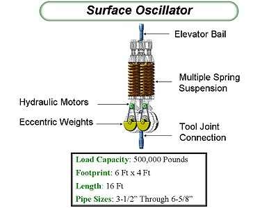
Surface Resonant Vibrators rely on the principle of counter rotating eccentric weights to impart a sinusoidal harmonic motion from the surface into the work string at the surface. Reference Three (above) provides a full explanation of this technology. The frequency of rotation, and hence vibration of the pipe string, is tuned to the resonant frequency of the system. The system is defined as the surface resonant vibrator, pipe string, fish and retaining media. The resultant forces imparted to the fish is based on the following logic:
- The delivery forces from the surface are a result of the static overpull force from the rig, plus the dynamic force component of the rotating eccentric weights
- Depending on the static overpull force component, the resultant force at the fish can be either tension or compression due to the sinusoidal force wave component from the oscillator
- Initially during startup of a vibrator, some force is necessary to lift and lower the entire load mass of the system. When the vibrator tunes to the resonant frequency of the system, the reactive load impedance cancels out to zero by virtue of the inductance reactance (mass of the system) equaling the compliance or stiffness reactance (elasticity of the tubular). The remaining impedance of the system, known as the resistive load impedance, is what is retaining the stuck pipe.
- During resonant vibration, a longitudinal sine wave travels down the pipe to the fish with an attendant pipe mass that is equal to a quarter wavelength of the resonant vibrating frequency.
- A phenomenon known as fluidization of soil grains takes place during resonant vibration whereby the granular material constraining the stuck pipe is transformed into a fluidic state that offers little resistance to movement of bodies through the media. In effect, it takes on the characteristics and properties of a liquid.
- During pipe vibration, Dilation and Contraction of the pipe body, known as Poisson's ratio, takes place such that when the stuck pipe is subjected to axial strain due to stretching, its diameter will contract. Similarly, when the length of pipe is compressed, its diameter will expand. Since a length of pipe undergoing vibration experiences alternate tensile and compressive forces as waves along its longitudinal axis (and therefore longitudinal strains), its diameter will expand and contract in unison with the applied tensile and compressive waves. This means that for alternate moments during a vibration cycle the pipe may actually be physically free of its bond.
References
- ↑ Patent number: 2972380, Filing date: Feb 20, 1956, Issue date: Feb 1961, Inventor: Albert G. Bodine Title: "Acoustic Method and Apparatus For Moving Objects Held Tight Within a Surrounding Medium"
- ↑ O. Gonzalez, "Retrieving Stuck Liners, Tubing, Casing And Drillpipe With Vibratory Resonant Techniques" Society of Petroleum Engineers Paper # 14759
- ↑ O. Gonzalez, Henry Bernat, Paul Moore, "The Extraction of Mud Stuck Tubing Using Vibratory Resonant Techniques" Society of Petroleum Engineers Paper # 109530