EMD 567
| EMD 567 | |
|---|---|
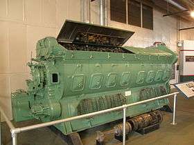 An EMD 16-567B on display at the North Carolina Transportation Museum. Shown in the foreground is an "exploded" Power Assembly, with the piston, piston carrier and piston rod (fork type) on the left, and the cylinder liner and cylinder head on the right. | |
| Overview | |
| Manufacturer | Electro-Motive Division of General Motors |
| Production | 1938–1966 |
| Combustion chamber | |
| Configuration | 45° Vee in V6, V8, V12, or V16 |
| Displacement |
3,405 to 9,080 cu in (55.8 to 148.8 L) 567.5 cu in (9.3 L) per cylinder |
| Cylinder bore | 8 1⁄2 in (216 mm) |
| Piston stroke | 10 in (250 mm) |
| Valvetrain | OHC |
| Compression ratio |
|
| Combustion | |
| Supercharger | One roots-type or clutch-driven |
| Turbocharger | Single |
| Fuel system | fuel injection |
| Management | Woodward governor |
| Fuel type | diesel |
| Output | |
| Power output |
600 to 2,500 hp (450 to 1,860 kW) |
| Chronology | |
| Successor | EMD 645 |
The EMD 567 is a line of large medium-speed diesel engines built by General Motors' Electro-Motive Division. This engine, which succeeded Winton's 201A, was used in EMD's locomotives from 1938 until its replacement in 1966 by the EMD 645. It has a bore of 8.5 in (216 mm), a stroke of 10 in (254 mm) and a displacement of 567 cu in (9.29 L) per cylinder. Like the 201A, the EMD 645 and the EMD 710, the EMD 567 is a two-stroke cycle engine. It is a V engine with an angle of 45° between cylinder banks (the 201A was 60° between cylinder banks; 45° later proved to be significant when EMD subsequently adapted the road switcher concept for most of its locomotives, and which required the narrower (albeit taller) engine which 45° provides). The 710, 645, and 567 are the only two-stroke engines commonly used today in locomotives. Eugene W. Kettering, son of Charles F. Kettering, joined Winton Engine in 1930. He moved to Detroit in 1936, and was a central figure in the development of the 567 and the Detroit Diesel 6-71. He moved to EMD in 1938, became Chief Engineer at EMD in 1948, then Division Director in 1956 and subsequently Research Assistant to the General Manager in 1958 until his retirement in 1960.[1]
In 1951, E. W. Kettering wrote a paper for the ASME entitled, History and Development of the 567 Series General Motors Locomotive Engine,[2] which goes into great detail about the technical obstacles that were encountered during the development of the 567 engine (these same considerations apply to the 645 and 710). The 567's designers started with a tabula rasa,[3] systematically eliminating each of the 201A's many deficiencies which were preventing the earlier design from becoming successful in freight service, although the 201A was relatively successful in the less-demanding passenger and switching services. The 567 design had nothing in common with the 201A except the two-stroke cycle itself: each and every component of the 201A was replaced with a new design, even the "dipstick", to paraphrase one of Kettering's off-handed comments. The 567 proved to be exceptionally successful in passenger, switching, freight, marine and stationary services, and, counting its two successors, the 645 and 710, which are not materially different from the 567 (all have the same external dimensions, differing mainly in per cylinder displacement), collectively have given nearly 80 years of exceptionally reliable service to those applications. As but one example of the achievements of the tabula rasa design: whereas the Winton 201A was doing very well with a 50,000-to-100,000-mile (80,000 to 161,000 km) piston lifetime, the 567 immediately achieved a 400,000-to-500,000-mile (640,000 to 800,000 km) piston lifetime, and in at least one case, reached a 1,000,000-mile (1,600,000 km) piston lifetime, a 10:1 to 20:1 improvement.[4]
567AC engines (an "A" block upgraded to "C" block specifications) and 567BC engines (a "B" block upgraded to "C" block specifications), both of which modifications eliminate the engine's "water deck" and substitute a "water manifold", as well as 567C and 567D engines, may be upgraded to use 645 power assemblies, theoretically achieving an increase in horsepower, but not without corresponding changes to the engine's Woodward governor which activates and controls the engine's "fuel rack". Although this power increase is not recommended, horsepower-for-horsepower updates (e.g., 2,000 hp or 1,500 kW 567D to 2,000 hp or 1,500 kW "645D"—645 power assemblies in a 567 block) are quite successful and common.
As 645 power assemblies are more readily available than 567 power assemblies, this upgrade may also be employed in so-called "life extension" programs, in which case the power assemblies would be upgraded, and the engine may be de-turbo-ed, without corresponding changes to the engine's Woodward governor, hence without a corresponding power increase.
Because of their age, 567 engines are generally exempt from emissions rules. EMD manufactures a special series of 645 power assemblies which are particularly useful in updating these exempt 567 engines and also certain exempt 645 engines.
EMD's chief competitor, GE, now makes EMD-compatible replacement parts.[5]
Specification

All 567 engines are two-stroke 45 degree V-engines. The engine is a uniflow design with four poppet-type exhaust valves in the cylinder head. For maintenance, a power assembly, consisting of a cylinder head, cylinder liner, piston, piston carrier, and piston rod, can be individually and relatively easily and quickly replaced. The block is made from flat, formed and rolled structural steel members and steel forgings welded into a single structure (a "weldment"). Blocks may, therefore, be easily repaired, if required, using conventional shop tools. Each bank of cylinders has an overhead camshaft which operates the exhaust valves and the unit injectors.[6]
The 567 is laid out with engine accessories (oil and water pumps and governors) at the "forward" end and the power take off at the "rear" end. The blowers and camshafts are at the "rear" end of the engine, with the blowers mounted above the power take off.[7]
All engines have mechanically-controlled unit injectors (patented in 1934 by General Motors, EMD's former owner).
See EMD 645 for general specifications common to all 567-645-710 engines.
All 567 engines utilize forced induction, with either a Roots blower or a turbocharger. The turbocharger (a combination turbo-compressor system) follows EMD's innovative design that uses a gear train and over-running clutch to drive the compressor rotor during low engine speed, when exhaust gas temperature (and, correspondingly, heat energy) alone is insufficient to drive the turbine. At higher engine speeds, increased exhaust gas temperature is sufficient to drive the turbine and the clutch disengages, turning the turbo-compressor system into a true turbocharger. The turbo-compressor can revert to compressor mode momentarily during demands for large increases in engine output power. While more expensive to maintain than Roots blowers, the turbocharger significantly reduces fuel consumption and emissions, while improving high-altitude performance. Additionally, EMD's turbo-compressor can provide a 50 percent increase in maximum rated horsepower over Roots-blown engines for the same engine displacement.
Horsepower for naturally aspirated engines (including Roots-blown two-stroke engines) is usually derated 2.5 percent per 1,000 feet (300 m) above mean sea level, a tremendous penalty at the 10,000 feet (3,000 m) or greater elevations which several Western U.S. and Canada railroads operate, and this can amount to a 25 percent power loss. Turbocharging effectively eliminates this derating.
Versions [8]
Numerous early improvements were aimed at increasing reliability and life, including a switch from the "U" shaped top (exhaust) well to a "V" shaped top well. This eliminated the cast top deck in favor of a fabricated (from plate steel) top deck, which had been the source of some early-life failures.[9] The 567 gave way to the 567A in 1941, which incorporated further top deck improvements and camshaft gear train changes.[10] The 567B followed in 1946 with minor improvements.[11] The 567C was released to further improve reliability and manufacturability. Visually, the 567C may be distinguished from earlier models by the presence of round (instead of square) handholes.[12]
The cost of a 16-567 in 1941 was US$24,000 (equivalent to $387,000 in 2015), and the cost of a 16-567B in 1951 was US$32,905 (equivalent to $300,000 in 2015).[2]
| Engine model | Max RPM | Aspiration | Dates built | Compression ratio |
6-cylinder | 8-cylinder | 12-cylinder. | 16-cylinder | Notes | ||||
|---|---|---|---|---|---|---|---|---|---|---|---|---|---|
| hp | kW | hp | kW | hp | kW | hp | kW | ||||||
| 567 | 800 | Roots blown | 9/38-3/43 | 16:1 | 600 | 447 | 1,000 | 746 | 1,350 | 1,007 | "U" Deck or "V" Deck versions were built with rectangular hand hole covers.[13] | ||
| 567A | 800 | Roots blown | 5/43-9/53 | 16:1 | 600 | 447 | 1,000 1,200 |
746 895 |
1,350 | 1,007 | Rectangular hand hole covers.[13] | ||
| 567B | 800 | Roots blown | 7/45-3/54 | 16:1 | 600 | 447 | 800 | 597 | 1,000 1,125 1,200 |
746 839 895 |
1,350 1,500 1,600 |
1,007 1,119 1,193 |
Rectangular hand hole covers.[13] |
| 567C | 800 835 |
Roots blown | 3/53-2/66 | 16:1 | 600 | 447 | 900 | 671 | 1,125 1,200 |
839 895 |
1,500 1,750 |
1,119 1,305 |
New crankcase design with round hand hole covers and replacing the water deck with water manifold piping.[13] |
| 567AC | 800 | Roots blown | 8/53-6/61 | 16:1 | 600 | 447 | 1,000 | 746 | Rebuild of 567A block to incorporate water manifold piping and to use 567C or certain 645 power assemblies | ||||
| 567BC | 800 | Roots blown | 9/53-10/63 | 16:1 | 1,125 1,200 |
839 895 |
1,500 | 1,119 | Production engine from September 1953 to May 1954 then used to rebuild 567Bs block to incorporate water manifold piping and to use 567C or certain 645 power assemblies | ||||
| 567CR | 835 | Roots blown | 10/56-11/65 | 16:1 | 900 | 671 | Reverse rotation | ||||||
| 567D1 | 835 | Roots blown | 12/59-11/65 | 20:1 | 1,325 | 988 | 1,800 | 1,342 | |||||
| 567D2 | 835 | Turbocharged | 11/59-4/62 | 14.5:1 | 2,000 | 1,491 | De-turbo-ed versions using 645 power assemblies, but still rated 2,000 hp are quite common[14] | ||||||
| 567D3 | 835 | Turbocharged | 7/58-11/63 | 14.5:1 | 2,250 2,400 |
1,678 1,790 |
De-turbo-ed versions using 645 power assemblies, but re-rated 2,000 hp are very rare | ||||||
| 567D3A | 900 | Turbocharged | 7/63-1/66 | 14.5:1 | 2,500 | 1,864 | De-turbo-ed versions using 645 power assemblies, but re-rated 2,000 hp are somewhat common | ||||||
| 567E | 835 | Roots blown | 2/66-4/66 | 16:1 | 1,200 | 895 | 2,000[15] [lower-alpha 1] |
1,491 | 645E block with 567C power assemblies[16] | ||||
Stationary/marine versions
Like most EMD engines, the 567 was also sold for stationary and marine applications.
Stationary and marine installations were available with either a left or right-hand rotating engine.
Marine engines differ from railroad and stationary engines mainly in the shape and depth of the engine's oil sump, which was altered to accommodate the rolling and pitching motions encountered in marine applications.
A pair of 12-567 engines powered one version of the Allies' LST vessels.
567C locomotive models
An EMD locomotive catalog, contemporary with the 567C, lists the following models:
| Locomotive | Prime Mover | Horsepower | Kilowatts | Purpose | Notes |
|---|---|---|---|---|---|
| F9 | 16-567C | 1,750 | 1,305 | 4-motor Freight or Passenger (Blomberg B trucks)[lower-alpha 2] | Derivatives FP9 and FL9 also produced, FL9 using Flexicoil Trucks |
| GP9 | 16-567C | 1,750 | 1,305 | 4-motor General Purpose Road Switcher (Blomberg B trucks) | |
| SD9 | 16-567C | 1,750 | 1,305 | 6-Motor Special Duty Road Switcher (Blomberg Flexicoil C trucks) | |
| E9 | 12-567C (x2) | 2,400 | 1,790 | 4-Motor Passenger Locomotive (Blomberg A1A trucks) | Two prime movers installed on same frame |
| SW600 | 6-567C | 600 | 447 | 100-Ton Yard Switcher (Blomberg AAR Type A switcher trucks)[lower-alpha 3] | |
| SW900 | 8-567C | 900 | 671 | 115-Ton Yard Switcher (AAR type A truck, Flexicoil B optional) | |
| SW1200 | 12-567C | 1,200 | 895 | 125-Ton Yard Switcher (AAR type A truck, Flexicoil B optional) | |
Most 567C locomotive models used D37B traction motors until mid 1959 when the D47B traction motor was used in production locomotives. Very early 567C locomotives from 1953 used the D27B traction motor.
567C and 567D engine maintenance
These two models are by far the most maintainable, with many 645 service parts being rather easily fitted to C and D engines.
The 567D's turbocharger is perhaps the least maintainable part of such an engine, and the 567D turbo has many more maintenance issues than 645E and later turbos. The wise choice is conversion of a 567D turbo engine to Roots-blown, thereby abandoning the turbo and its many issues. Installation of 645 power assemblies will still allow Roots-converted 4-axle locomotives (GP20s) to produce 2,000 hp (1,500 kW), as does a Roots-blown 16-645E, thereby becoming the functional equivalent of a GP38, although with older electrical equipment and controls, and, of course, the older carbody.
Many EMD locomotives with C and D engines are still operating, particularly as their relatively light weight (about 260,000 pounds or 120,000 kilograms) is of significant benefit to shortline and industrial operators.
See also
Notes
- ↑ Figure from 16V 567E engine installed in RENFE Class 319.2
- ↑ Blomberg B trucks are common on competitive road switchers, e.g. early ALCo and GE four-axle road switchers, as many purchasers elected to re-use traded-in Blomberg B trucks; otherwise AAR Type B road trucks are often found; Indeed a few EMD road locomotives were supplied with reclaimed AAR Type B road trucks, mainly to save cost.
- ↑ Blomberg Flexicoil B lightweight road trucks were optional.
References
- ↑ "Biography of Charles F., Eugene, and Virginia Kettering". OhioLINK. Retrieved 6 January 2015.
- 1 2 Kettering, E.W. (29 November 1951). History and Development of the 567 Series General Motors Locomotive Engine (PDF). ASME 1951 Annual Meeting. Atlantic City, New Jersey: Electro-Motive Division, General Motors Corporation. Retrieved 6 January 2015.
- ↑ Kettering (1951); p.14.
"In time most of the early bugs were cleaned up, but it was becoming more evident that to make a substantial gain in the durability of the 201A engine a major redesign would be in order. The diesel locomotive was rapidly proving itself and to the more optimistic it looked like it was going to be a good business, so it was decided that the engine would be redesigned for railroad use only. The design would not be handicapped by requirements for marine, Navy, or stationary application. Most of the Winton experimental design group moved to Detroit where the redesign was to be made. After settling in Detroit we took a large piece of paper and on one side wrote down all of the troubles which were known in the 201A engine at that time. On the other side we were going to write down parts of the engine which had been satisfactory. These items were based on the four years experience in the field and the test work at Winton and General Motors Research. It did not take long to fill in one side of the sheet. In fact, the more we looked into what we could salvage of the 201A design to correct all of these troubles the more apparent it was that we should start with a clean piece of paper and forget the 201A." - ↑ Kettering (1951); p. 29.
"A brief comparison can be drawn as to life of pistons in passenger service. These comparisons must be based on passenger operation as there never were any 201As in any other service than passenger and switcher. The 201A aluminum piston at the very beginning did not run 50,000 miles and the later 201A pistons ran a questionable 100,000 miles in hard service. The average life of the first 567 piston was in the range of 400,000 to 500,000. On one major railroad the average life of the current design two-piece piston is at least one million miles (Fig. 24)." - ↑ "Stationary Parts". GE Transportation. Archived from the original on 3 December 2010. Retrieved 6 January 2015.
- ↑ Challen, Bernard; Baranescu, Rodica Baranescu, eds. (1999). Diesel Engine Reference Book (Second ed.). Butterworth-Heinemann. p. 598. ISBN 0-7506-2176-1.
- ↑ Kettering (1951); p. 17.
"The full line of engines was designed with the same general arrangement, revising basically only the length of crankshaft and crankcase to accomodate [sic] the required number of cylinders. It appeared that the most satisfactory method of having the engine accessories such as pumps, governor, etc. easily maintained would be to drive them through a gear train at the forward end of the engine, that is, opposite the power take-off end. Having the location of the pumps all at one end of the engine, called the accessory drive end, fitted very well into locomotive installation. A leaf spring flexible drive gear mounted on the crankshaft was used to eliminate all crankshaft torsional vibration from the gear train.
"By using either one or two blowers for an 8 or 12 cylinder engine respectively and mounting them above the main generator, it was possible to shorten the overall length of the engine and generator installation. This was one of the main original objectives. The blowers as well as the camshafts were driven at the power take-off end of the engine by another gear train." - ↑ Pinkepank, Jerry A (1973). The Second Diesel Spotter’s Guide. Kalmbach Books. p. 26. LCCN 66-22894.
- ↑ Kettering (1951); pp. 57–58.
"Much field difficulty was experienced, particularly in the weld of the stress plate to the cast steel top deck. This difficulty can be blamed on two things. First, we were attempting to weld to cast steel which in some cases contained burned-in sand. This made welding inadequate due to slag inclusions, etc. Second, we were attempting to automatically weld against a back-up strip which in some cases did not fuse properly, leaving a bad notch effect which, of course, increased stress beyond working limits and fatigue failures resulted. There were approximately 600 of these crankcases made, twelve of which were 16s. Only four of these twelve were placed in railroad service. They were retired after about three years of service. A retirement program is now in effect for all of these cast top deck crankcases. A new crankcase was developed and went into production in early 1940 using a fabricated top deck, and can be most readily identified by a change in the exhaust well of the engine, which lies between the V's from U shape to a V shape. This design simplified top deck machining, eliminated the studding of the cast top deck by replacing the studs with through bolts retained by crabs at the bottom of the pots and crabs at the top of the cylinder heads, using self-aligning spherical washers and nuts (See Figure 49)." - ↑ Kettering (1951); p. 59.
"By 1941 it was desirable to further simplify the crankcase, and the flat top deck Model 567 A crankcase was developed. This crankcase was first used on the 12 cylinder LST engines which started in production early in 1942. The crankcase incorporated a flat tie plate the full length of the engine which provided a flat surface for mounting exhaust manifolds and lift hooks (See Figure 50).
"It was at this time that the gear train was simplified from four to two idler gears as explained previously. The cast steel cylinder head retainers were simplified over the second 567 design." - ↑ Kettering (1951) pp.59–60.
"In 1946 a new line of crankcases, designated as the 567B, were introduced which were basically the same as the 567A except for a change to permit the mounting of the auxiliary generator drive gear. About three or four months after the introduction of the "B" engine the cylinder head retainer castings, which had been a continuous source of production problems, were replaced with steel forgings." - ↑ Kettering (1951); pp. 61–64.
"We are in the final stages of developing a new crankcase to be known as the Model 567C which will further improve our product. One premise of this design has been to eliminate water on any stressed member of the crankcase because of corrosion difficulties. In the earlier crankcases just described, cracks have occurred in the area of the cooling water which were caused by corrosion fatigue (See Fig. 52).
[...] "The entire fabrication has been simplified through the use of heavy rolled sections to make up the main stress members. Complex forgings are used in the top deck in place of the many steel stampings, thereby reducing a tremendous amount of fitting and manual welding." - 1 2 3 4 Cook, Preston (1 March 2006). "The EMD 567 Engine in the 21st Century". Railway Preservation News. Archived from the original on 19 October 2013. Retrieved 6 January 2015.
- ↑ Pinkepank, Jerry A.; Marre, Louis A. (1979). Diesel Spotters Guide Update. Kalmbach Books. pp. 128–129. ISBN 0-89024-029-9.
- ↑ "Anexo I, Características de los Vehículos" (PDF). www.vialibre-ffe.com (in Spanish). Renfe. 7 March 2010. pp. 2–3.
- ↑ These "composite" engines were constructed using 645E blocks and all the remaining components from 567C or D engines, as required to meet contracts for 567-powered locomotives after the 567 engine had been discontinued, and all new block production was 645E.
Bibliography
- Pinkepank, Jerry A (1973). The Second Diesel Spotter’s Guide. Milwaukee, Wisconsin: Kalmbach Books. ISBN 0-89024-026-4. LCCN 66-22894.
- Service Department (1954?). The Complete Line of General Motors Diesel Locomotives. La Grange, IL: Electro-Motive Division of General Motors Corporation
External links
- Kettering, E.W. (29 November 1951). History and Development of the 567 Series General Motors Locomotive Engine (PDF). ASME 1951 Annual Meeting. Atlantic City, New Jersey: Electro-Motive Division, General Motors Corporation. Retrieved 6 January 2015.
- Houk, Randy (14 December 2012). "The History of EMD Diesel Engines". Pacific Southwest Railway Museum. Archived from the original on 22 July 2014. Retrieved 5 January 2015.
- "EMD 567 Diesel Engine (1938 EMD Advertisement)". Pacific Southwest Railway Museum. 14 December 2010. Archived from the original on 12 May 2014. Retrieved 5 January 2015.
- "Engine Maintenance Manual No. 252C for Model 567C Engines, 3rd Edition" (PDF). fallenflags. January 1957. Retrieved 17 June 2016.