Fire control tower
A fire control tower is a structure located near the coastline, used to detect and locate enemy vessels offshore, direct fire upon them from coastal batteries, or adjust the aim of guns by spotting shell splashes.
The U.S. Coast Artillery fire control system included many fire control towers, which were used between about 1900 and the end of WW2.[lower-alpha 1]
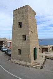
A typical fire control tower
A fire control tower usually contained several fire control stations, known variously as observation posts (OPs), base end stations, or spotting stations from which observers searched for enemy ships, fed data on target location to a plotting room, or spotted the fall of fire from their battery, so the aim of the guns could be adjusted. For example, the fire control tower at Site 131-1A contained one OP, two base end stations, and two spotting stations. A shorthand notation was used to identify the stations.
For instance, the top story of Site 131-1A was planned to contain base end station #3 and spotting station #3 for Battery #15. The overall plan document for the harbor defenses contained a list that linked the tactical numbers of all batteries to their names.[lower-alpha 2] That document also contained an organization chart that identified all the Command (C) and Group (G) codes, like "G3."[lower-alpha 3]
These towers were arrayed in networks along the coast on either side of the artillery batteries they supported. The number and height of the towers was determined by the range of the guns involved. Many fire control towers were also part of a harbor's antiaircraft warning system. Spotters occupied cramped "crow's nests" on the top floors of the towers that enabled them to lift a trapdoor in the tower's roof and scan the sky for approaching aircraft.
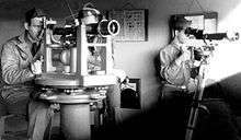
When an enemy surface craft was detected, bearings to it were measured from a pair of towers, using instruments like azimuth scopes or depression position finders. Since the distances along the line between the towers (called a baseline) had already been precisely measured by surveyors, the length of this baseline, plus the two bearing angles from two stations at the ends of the line (also called base end stations) to the target, could be used to plot the position of the target by a mathematical process called triangulation.[lower-alpha 4]
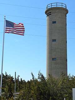
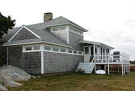
A fire control tower was usually five to ten stories tall, depending on the height of the site at which it was built and the area it had to cover. Often made of poured concrete, its lower floors were usually unoccupied and were capped by occupied observation levels. Staircases ran up to the lowest observation level, and wooden ladders were then used to climb to higher levels. But some fire control structures built atop coastal hills or bluffs only needed to be one- or two-story buildings, and were built of wood or brick. Sometimes these buildings were camouflaged as private homes, and were referred to as fire control "cottages."[lower-alpha 5]
The center of octagonal concrete mounting pad on the eight floor of 131-1A (which was meant to support a depression position finder) was usually the surveyed point at the end of the baseline (and thus the precise location of the base end station).[lower-alpha 6] A survey marker embedded in the tower's roof directly above this pad defined this point. Other observing instruments on lower floors of the tower were usually lined up directly beneath the eighth floor mounting pad and the rooftop marker, so they shared the same latitude and longitude. The pipe stands shown on floors six and seven of the Nahant Site 131-1A tower probably held azimuth scopes, which were less complex telescopes that determined bearings to a target but not its range from the tower.
Site 131-1A had electric lights, phones, and radio communications, and a time interval bell that was used for coordinating fire control information. Some fire control towers were also the mounting points for coast surveillance or fire control radar antennas. Although our sample tower has a simple, square appearance, some versions of these towers in New England had round or partly octagonal plans.
A network of fire control structures
Each major battery of Coast Artillery guns was supported by a network of fire control structures (towers, cottages, or buildings) which were spread out along the nearby coast.[lower-alpha 7] Guns of longer range had larger numbers of fire control stations in their networks. Depending on where the target ship was located and upon other tactical conditions, one or more of these stations would be selected to control the fire from a given battery on that target.
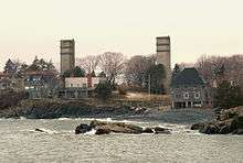
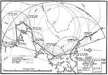
For a WW2-era example, take Battery Murphy, the two 16-inch (410 mm) guns in Nahant, MA. Murphy used ten fire control stations that made up Battery Murphy's fire control network, which was spread out over about forty miles of coastline running from Station 1 (Fourth Cliff) in the south to Station 10 (Castle Hill) in the north. Half of these stations were located in tall towers, and half in low-rise cottages.
The length of the baselines running between each pair of stations was known very precisely. For example, Station #1 and Station #2 were 12,249.63 yards (6.96 mi; 11.2 km) apart. These distances were plugged into the triangulation equations for the pair of stations involved in sighting on a particular target in order to compute its position.[lower-alpha 8] As the target ship moved along the coast, different pairs of fire control stations (and therefore different baselines) would come into play. Very precise measurements were also taken of the distance between the directing point of each battery (often the pintle center of its Gun #1) and each fore control station's observing point. These distance could also be used for target location, if one of the observations was taken from the battery itself and another from the distant station.
Gallery
-

A plan of all the floors of Nahant Site 1A
-
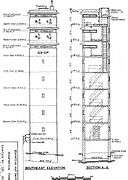
Elevation drawings of Nahant Site 131-1A
-
Fire control tower at Ft. Monroe, VA
-
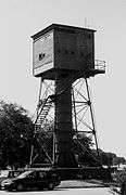
A fire control tower at Ft. Monroe, VA
-
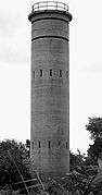
A fire control tower at Ft. Miles, DE
-
Fire Control Tower 23, also part of Fort Miles, but across the Delaware Bay in New Jersey
-

Triangulation using two fire control towers
-
This building contained two base end stations and an observation post
-
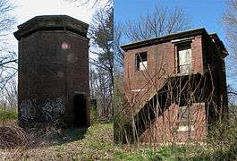
Composite view of 1904 East Side fire control structure at Ft. Andrews, Peddocks Island, MA
-

Fire control position at Fort Funston, CA, modified as a hang glider platform
-

Former Harbor Entrance Control Post disguised as a mansion, Fort Burnside, Jamestown, RI
-
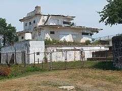
Former Harbor Entrance Control Post-Harbor Defense Command Post disguised as a mansion, Fort Stark, New Castle, NH
-

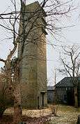
Former fire control tower resembling a lighthouse, Hull, MA
Footnotes
- ↑ About 200 fire control towers once existed in the states of ME, NH, and MA alone, and perhaps 1,000 of these structures were built in the U.S. as a whole. Today, many of these towers have been demolished, but many others have survived, often on private property or in state or federal parks or reservations.
- ↑ For Boston Harbor in WW2, 16 batteries of guns were initially planned. Two of the major batteries, Tactical Nos. 12 and 13 at Ft. Dawes on Deer Island, were never finished, bringing the actual total number of batteries to 14. Depending upon the type of document being considered, however, these numbers might vary, contributing to confusion in describing the organization of the harbor defenses.
- ↑ The codes for the various batteries and command units at a given harbor could get confusing, since sometimes batteries were added or deleted and commands were reorganized between the time the plans were drawn up and the time the guns were mounted or the fire control towers were built. A lot of cross-checking among documents is sometimes needed to clarify the true assignments. For our sample fire control tower, the 6th floor ended up housing an observation post for the command of the northern guns defending Boston Harbor. The seventh floor held a base end station and a spotting station for Battery 206, the pair of 6-inch (150 mm) guns nearby at East Point. The eighth floor was to have held a similar pair of stations for the two 16-inch (410 mm) guns at Fort Dawes on Deer Island, but those guns were never installed, so the use of the top floor is unclear. Also on the top floor was the "crow's nest" antiaircraft spotting post and its roof trapdoor.
- ↑ Prior to WW2 (and sometimes throughout the war) a mechanical analog computer called a plotting board was used to calculate firing data for coast artillery batteries. These devices were located in plotting rooms which were usually protected in earth-covered reinforced concrete bunkers or in the casemates of the larger gun batteries themselves. Later in the war, the electro-mechanical gun data computer received target coordinate data directly from observing instruments in fire control towers or from fire control radars and performed the triangulation calculations automatically. Gun data computers brought greater speed and accuracy to the fire control process.
- ↑ Sometimes (particularly early in the WW2 years) pre-existing structures, like water towers or seaside hotels featuring tall lookouts, were used as fire control towers. These installations were already naturally camouflaged.
- ↑ The point surveyed was usually the "pintle center" of the instrument.
- ↑ In the early days of the Coast Artillery Corps (c. 1900-1915), most batteries would be controlled from a single vertical baseline fire control station located at the Battery Commander's position, in a nearby fire control building, or even in the concrete crow's nest of the battery casemate itself. As longer-range guns were developed and the superior accuracy of the horizontal baseline system of fire control was recognized, most major batteries (of 6-inch (150 mm) guns or larger) would be served by two, or sometimes three, base end/spotting stations. By WW2, longer-range guns required larger networks of base end and spotting stations, usually located in towers or cottages.
- ↑ If a more modern gun data computer were being used, the bearing angles and the baseline length from the two towers were input to the computer, where the triangulation equation was solved and firing data computed. If an older plotting board were being used, the plotting room crew received bearing angles to the target from each station and then used the plotting board to calculate firing data for the guns.
References
See also
- Fire lookout tower, used to spot wild fires
- base end station
- Coast Artillery fire control system
- Flak tower, similar large concrete towers built during WWII for anti-aircraft defense.