Framebuffer
A framebuffer (frame buffer, or sometimes framestore) is a portion of RAM[1] containing a bitmap that is used to refresh a video display from a memory buffer containing a complete frame of data.[2]
The information in the memory buffer typically consists of color values for every pixel to be shown on the display. Color values are commonly stored in 1-bit binary (monochrome), 4-bit palettized, 8-bit palettized, 16-bit high color and 24-bit true color formats. An additional alpha channel is sometimes used to retain information about pixel transparency. The total amount of memory required for the framebuffer depends on the resolution of the output signal, and on the color depth and palette size.
History
Computer researchers had long discussed the theoretical advantages of a framebuffer, but were unable to produce a machine with sufficient memory at an economically practicable cost. In 1969, A. Michael Noll of Bell Labs implemented a scanned display with a frame buffer.[3][4] Later on, the Bell Labs system was expanded to display an image with a color depth of three bits on a standard color TV monitor. An even earlier scanned display was implemented at the Brookhaven National Laboratory.[5] Advances in integrated-circuit memory in the 1970s made it more cost practical to create framebuffers capable of holding a standard video image.
In 1972, Richard Shoup developed the SuperPaint system at Xerox PARC.[6] This system had 311,040 bytes of memory and was capable of storing 640 by 480 pixels of data with 8 bits of color depth. The memory was scattered across 16 circuit boards, each loaded with multiple 2-kilobit shift register chips. While workable, this design required that the total framebuffer be implemented as a 307,200 byte shift register that shifted in synchronization with the television output signal. The primary drawback to this scheme was that memory was not random access. Rather, a given position could be accessed only when the desired scan-line and pixel time rolled around. This gave the system a maximum latency of 33 ms for writing to the framebuffer.
Shoup was also able to use the SuperPaint framebuffer to create an early digital video-capture system. By synchronizing the output signal to the input signal, Shoup was able to overwrite each pixel of data as it shifted in. Shoup also experimented with modifying the output signal using color tables. These color tables allowed the SuperPaint system to produce a wide variety of colors outside the range of the limited 8-bit data it contained. This scheme would later become commonplace in computer framebuffers.
In 1974 Evans & Sutherland released the first commercial framebuffer, costing about $15,000. It was capable of producing resolutions of up to 512 by 512 pixels in 8-bit grayscale, and became a boon for graphics researchers who did not have the resources to build their own framebuffer. The New York Institute of Technology would later create the first 24-bit color system using three of the Evans & Sutherland framebuffers.[7] Each framebuffer was connected to an RGB color output (one for red, one for green and one for blue), with a Digital Equipment Corporation PDP 11/04 minicomputer controlling the three devices as one.
In 1975, the UK company Quantel produced the first commercial full-color broadcast framebuffer, the Quantel DFS 3000. It was first used in TV coverage of the 1976 Montreal Olympics to generate a picture-in-picture inset of the Olympic flaming torch while the rest of the picture featured the runner entering the stadium.
The rapid improvement of integrated-circuit technology made it possible for many of the home computers of the late 1970s (such as the Apple II) to contain low-color framebuffers. While initially derided for poor performance in comparison to the more sophisticated graphics devices used in computers like the Atari 400, framebuffers eventually became the standard for all personal computers. Today, nearly all computers with graphical capabilities utilize a framebuffer for generating the video signal.
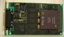
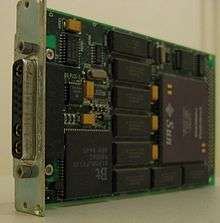
Framebuffers also became popular in high-end workstations and arcade system boards throughout the 1980s. SGI, Sun Microsystems, HP, DEC and IBM all released framebuffers for their workstation computers. These framebuffers were usually of a much higher quality than could be found in most home computers, and were regularly used in television, printing, computer modeling and 3D graphics. Framebuffers were also used by Sega for its high-end arcade boards, which were also of a higher quality than on home computers.
Amiga computers, due to their special design attention to graphics performance, created in the 1980s a vast market of framebuffer based graphics cards. Noteworthy to mention was the graphics card in Amiga A2500 Unix, which was in 1991 the first computer to implement an X11 server program as a server for hosting graphical environments and the Open Look GUI graphical interface in high resolution (1024x1024 or 1024x768 at 256 colors). The graphics card for A2500 Unix was called the A2410 (Lowell TIGA Graphics Card) and was an 8-bit graphics board based on the Texas Instruments TMS34010 clocked at 50 MHz. It was a complete intelligent graphics coprocessor. The A2410 graphics card for Amiga was co-developed with Lowell University. Other noteworthy Amiga framebuffer based cards were: the Impact Vision IV24 graphics card from GVP, an interesting integrated video suite, capable of mixing 24-bit framebuffer, with Genlock, Chromakey, TV signal pass-thru and TV in a window capabilities; the DCTV an external graphics adapter and video capture system; the Firecracker 32-bit graphics card; the Harlequin card, the Colorburst; the HAM-E external framebuffer. The Graffiti external graphics card is still available on the market.
Most Atari ST (Mega STE model), and Atari TT framebuffers were created for the VME rear connector slot of Atari machines dedicated to video expansion cards: Leonardo 24-bit VME graphics adapter, CrazyDots II 24-bit VME graphics card, Spektrum TC graphics card, NOVA ET4000 VME SVGA graphics card (capable of resolutions up to 1024x768 at 256 colors or 800x600 at 32768 colors), whose design came from the ISA/PC world (it was effectively an ATI Mach32 S: with 1 MB of video RAM).
Display modes
Framebuffers used in personal and home computing often had sets of defined "modes" under which the framebuffer could operate. These modes would automatically reconfigure the hardware to output different resolutions, color depths, memory layouts and refresh rate timings.
In the world of Unix machines and operating systems, such conveniences were usually eschewed in favor of directly manipulating the hardware settings. This manipulation was far more flexible in that any resolution, color depth and refresh rate was attainable – limited only by the memory available to the framebuffer.
An unfortunate side-effect of this method was that the display device could be driven beyond its capabilities. In some cases this resulted in hardware damage to the display.[8] More commonly, it simply produced garbled and unusable output. Modern CRT monitors fix this problem through the introduction of "smart" protection circuitry. When the display mode is changed, the monitor attempts to obtain a signal lock on the new refresh frequency. If the monitor is unable to obtain a signal lock, or if the signal is outside the range of its design limitations, the monitor will ignore the framebuffer signal and possibly present the user with an error message.
LCD monitors tend to contain similar protection circuitry, but for different reasons. Since the LCD must digitally sample the display signal (thereby emulating an electron beam), any signal that is out of range cannot be physically displayed on the monitor.
Color palette
Framebuffers have traditionally supported a wide variety of color modes. Due to the expense of memory, most early framebuffers used 1-bit (2-color), 2-bit (4-color), 4-bit (16-color) or 8-bit (256-color) color depths. The problem with such small color depths is that a full range of colors cannot be produced. The solution to this problem was to add a lookup table to the framebuffers. Each "color" stored in framebuffer memory would act as a color index; this scheme was sometimes called "indexed color".
The lookup table served as a palette that contained data to define a limited number (such as 256) of different colors. However, each of those [256] colors, itself, was defined by more than 8 bits, such as 24 bits, eight of them for each of the three primary colors. With 24 bits available, colors can be defined far more subtly and exactly, as well as offering the full range gamut which the display can show. While having a limited total number of colors in an image is somewhat restrictive, nevertheless they can be well chosen, and this scheme is markedly superior to 8-bit color.
The data from the framebuffer in this scheme determined which of the [256] colors in the palette was for the current pixel, and the data stored in the lookup table (sometimes called the "LUT") went to three digital-to-analog converters to create the video signal for the display.
The framebuffer's output data, instead of providing relatively crude primary-color data, served as an index – a number – to choose one entry in the lookup table. In other words, the index determined which color, and the data from the lookup table determined precisely what color to use for the current pixel.
In some designs it was also possible to write data to the LUT (or switch between existing palettes) on the run, allowing to divide the picture into horizontal bars with their own palette and thus render an image that had a far wider [than X colors] palette. For example, viewing an outdoor shot photograph, the picture could be divided into four bars, the top one with emphasis on sky tones, the next with foliage tones, the next with skin and clothing tones, and the bottom one with ground colors. This required each palette to have overlapping colors, but carefully done, allowed great flexibility.
Memory access
While framebuffers are commonly accessed via a memory mapping directly to the CPU memory space, this is not the only method by which they may be accessed. Framebuffers have varied widely in the methods used to access memory. Some of the most common are:
- Mapping the entire framebuffer to a given memory range.
- Port commands to set each pixel, range of pixels or palette entry.
- Mapping a memory range smaller than the framebuffer memory, then bank switching as necessary.
The framebuffer organization may be chunky (packed pixel) or planar.
RAM on the video card
Video cards always have a certain amount of RAM. This RAM is also called the frame buffer. Video card RAM is necessary to keep the entire screen image in memory. The CPU sends its data to the video card. The video processor forms a picture of the screen image and stores it in the frame buffer. This picture is a large bit map. It is used to continually update the screen image.[9] The term video card or 'Graphics Card' can also be synonymous with a GPU, Graphics Processor Unit, because a Graphics Card must contain a GPU, and a GPU requires a board to be mounted on (that's the 'card' part).
Virtual framebuffers
Many systems attempt to emulate the function of a framebuffer device, often for reasons of compatibility. The two most common "virtual" framebuffers are the Linux framebuffer device (fbdev) and the X Virtual Framebuffer (Xvfb). The X Virtual Framebuffer was added to the X Window System distribution to provide a method for running X without a graphical framebuffer. While the original reasons for this are lost to history, it is often used on modern systems to support programs such as the Sun Microsystems JVM that do not allow dynamic graphics to be generated in a headless environment.
The Linux framebuffer device was developed to abstract the physical method for accessing the underlying framebuffer into a guaranteed memory map that is easy for programs to access. This increases portability, as programs are not required to deal with systems that have disjointed memory maps or require bank switching.
Page flipping
Since framebuffers are often designed to handle more than one resolution, they often contain more memory than is necessary to display a single frame at lower resolutions. Since this memory can be considerable in size, a trick was developed to allow for new frames to be written to video memory without disturbing the frame that is currently being displayed.
The concept works by telling the framebuffer to use a specific chunk of its memory to display the current frame. While that memory is being displayed, a completely separate part of memory is filled with data for the next frame. Once the secondary buffer is filled (typically referred to as the "back buffer"), the framebuffer is instructed to look at the secondary buffer instead. The primary buffer (typically referred to as the "front buffer") becomes the secondary buffer, and the secondary buffer becomes the primary. This switch is often done after the vertical blanking interval to prevent the screen from "tearing" (i.e., half the old frame is shown, and half the new frame is shown).
Most modern framebuffers are manufactured with enough memory to perform this trick even at high resolutions. As a result, it has become a standard technique used by PC game programmers.
Graphics accelerators
As the demand for better graphics increased, hardware manufacturers created a way to decrease the amount of CPU time required to fill the framebuffer. This is commonly called "graphics accelerating".
Common graphics drawing commands (many of them geometric) are sent to the graphics accelerator in their raw form. The accelerator then rasterizes the results of the command to the framebuffer. This method can save thousands or millions of CPU cycles per command, as the CPU is freed to do other work.
While early accelerators focused on improving the performance of 2D GUI systems, most modern accelerators focus on producing 3D imagery in real time. A common design is to send commands to the graphics accelerator using a library such as OpenGL or Direct3D. The graphics driver then translates those commands to instructions for the accelerator's graphics processing unit (GPU). The GPU uses those microinstructions to compute the rasterized results. Those results are bit blitted to the framebuffer. The framebuffer's signal is then produced in combination with built-in video overlay devices (usually used to produce the mouse cursor without modifying the framebuffer's data) and any analog special effects that are produced by modifying the output signal. An example of such analog modification was the spatial anti-aliasing technique used by the 3dfx Voodoo cards. These cards add a slight blur to output signal that makes aliasing of the rasterized graphics much less obvious.
At one time there were many manufacturers of graphics accelerators, including: 3dfx; ATI; Hercules; Trident; Nvidia; Radius; S3 Graphics; SiS and Silicon Graphics. As of 2015 the market for graphics accelerators for x86-based systems is dominated by Nvidia (purchased 3dfx from 2002), AMD (who purchased ATI in 2006), and Intel (which currently produces only integrated GPUs rather than discrete video cards).
Comparisons to other display technologies
Framebuffers differ significantly from the vector displays that were common prior to the advent of faster graphics (and, consequently, to the concept of a framebuffer). With a vector display, only the vertices of the graphics primitives are stored. The electron beam of the output display is then commanded to move from vertex to vertex, tracing an analog line across the area between these points. With a framebuffer, the electron beam (if the display technology uses one) is commanded to trace a left-to-right, top-to-bottom path across the entire screen, the way a television renders a broadcast signal. The color information for each point thus displayed on the screen is pulled from the framebuffer, creating a set of discrete picture elements, i.e. pixels.
Likewise, framebuffers differ from the technology used in early text displays, where a buffer holds codes for characters, not individual pixels. The video display device drives the electron beam in a raster pattern the same as with a framebuffer, but generates the pixels of each character in the buffer as it directs the beam.
See also
References
- ↑ "What is frame buffer? A Webopedia Definition". webopedia.com.
- ↑ "Frame Buffer FAQ". Retrieved 14 May 2014.
- ↑ Noll, A. Michael, "Scanned-Display Computer Graphics," Bell Telephone Laboratories, Technical Memorandum, TM69-1234-8, November 21, 1969.
- ↑ Noll, A. Michael, “Scanned-Display Computer Graphics,” Communications of the ACM, Vol. 14, No. 3, (March 1971), pp. 145-150.
- ↑ Ophir, S., S. Rankowitz, B. J. Shepherd, and R. J. Spinrad, "BRAD: The Brookhave Raster Display," Comm. ACM, Vol. 11, No. 6 (June 1968), pp. 415-416.
- ↑ Richard Shoup (2001). "SuperPaint: An Early Frame Buffer Graphics System" (PDF). IEEE Annals of the History of Computing.
- ↑ "History of the New York Institute of Technology Graphics Lab". Retrieved 2007-08-31.
- ↑ http://tldp.org/HOWTO/XFree86-Video-Timings-HOWTO/overd.html XFree86 Video Timings HOWTO: Overdriving Your Monitor
- ↑ "An illustrated Guide to the Video Cards". karbosguide.com.
- Notes
- Alvy Ray Smith (May 30, 1997). "Digital Paint Systems: Historical Overview" (PDF). Microsoft Tech Memo 14.
- Wayne Carlson (2003). "Hardware advancements". A Critical History of Computer Graphics and Animation. The Ohio State University.
- Alvy Ray Smith (2001). "Digital Paint Systems: An Anecdotal and Historical Overview" (PDF). IEEE Annals of the History of Computing.
External links
- Interview with NYIT researcher discussing the 24-bit system
- Jim Kajiya – Designer of the first commercial framebuffer
- History of Sun Microsystems' Framebuffers
- DirectFB – An abstraction layer on top of the Linux Framebuffer device
- pxCore - A portable framebuffer abstraction layer for Windows, Windows Mobile, Linux and OSX.