Function block diagram
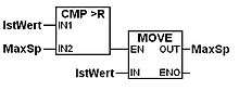
The Function Block Diagram (FBD) is a graphical language for programmable logic controller design,[1] that can describe the function between input variables and output variables. A function is described as a set of elementary blocks. Input and output variables are connected to blocks by connection lines.
Inputs and outputs of the blocks are wired together with connection lines, or links. Single lines may be used to connect two logical points of the diagram:
- An input variable and an input of a block
- An output of a block and an input of another block
- An output of a block and an output variable
The connection is oriented, meaning that the line carries associated data from the left end to the right end. The left and right ends of the connection line must be of the same type.
Multiple right connection, also called divergence can be used to broadcast information from its left end to each of its right ends. All ends of the connection must be of the same type.
Function Block Diagram is one of five languages for logic or control configuration[2] supported by standard IEC 61131-3 for a control system such as a Programmable Logic Controller (PLC) or a Distributed Control System (DCS). The other supported languages are ladder logic, sequential function chart, structured text, and instruction list.
See also
References
| Wikimedia Commons has media related to Function block diagrams. |