Gummel–Poon model
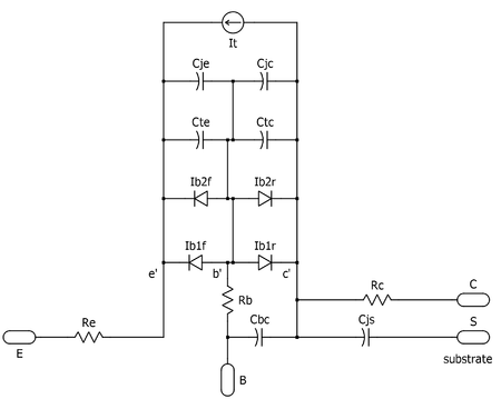
Schematic of Spice Gummel-Poon Model NPN
The Gummel–Poon model is a model of the bipolar junction transistor. It was first described in a paper published by Hermann Gummel and H. C. Poon at Bell Labs in 1970.[1]
The Gummel–Poon model and modern variants of it are widely used via incorporation in the popular circuit simulators such as SPICE. A significant effect that the Gummel–Poon model accounts for is the variation of the transistors'  and
and  values with the direct current level. When certain parameters are omitted, the Gummel–Poon model reduces to the simpler Ebers–Moll model.[1]
Model parameters
Spice Gummel–Poon model parameters
| # | Name | Property Modeled | Parameter | Units | Default Value |
|---|---|---|---|---|---|
| 1 | IS | current | transport saturation current | A | 1.00E-016 |
| 2 | BF | current | ideal max forward beta | - | 100 |
| 3 | NF | current | forward current emission coefficient | - | 1 |
| 4 | VAF | current | forward Early voltage | V | inf |
| 5 | IKF | current | corner for forward beta high current roll-off | A | inf |
| 6 | ISE | current | B-E leakage saturation current | A | 0 |
| 7 | NE | current | B-E leakage emission coefficient | - | 1.5 |
| 8 | BR | current | ideal max reverse beta | - | 1 |
| 9 | NR | current | reverse current emission coefficient | - | 1 |
| 10 | VAR | current | reverse Early voltage | V | inf |
| 11 | IKR | current | corner for reverse beta high current roll-off | A | inf |
| 12 | ISC | current | B-C leakage saturation current | A | 0 |
| 13 | NC | current | B-C leakage emission coefficient | - | 2 |
| 14 | RB | resistance | zero-bias base resistance | ohms | 0 |
| 15 | IRB | resistance | current where base resistance falls half-way to its minimum | A | inf |
| 16 | RBM | resistance | minimum base resistance at high currents | ohms | RB |
| 17 | RE | resistance | emitter resistance | ohms | 0 |
| 18 | RC | resistance | collector resistance | ohms | 0 |
| 19 | CJE | capacitance | B-E zero-bias depletion capacitance | F | 0 |
| 20 | VJE | capacitance | B-E built-in potential | V | 0.75 |
| 21 | MJE | capacitance | B-E junction exponential factor | - | 0.33 |
| 22 | TF | capacitance | ideal forward transit time | s | 0 |
| 23 | XTF | capacitance | coefficient for bias dependence of TF | - | 0 |
| 24 | VTF | capacitance | voltage describing VBC dependence of TF | V | inf |
| 25 | ITF | capacitance | high-current parameter for effect on TF | A | 0 |
| 26 | PTF | excess phase at freq=1.0/(TF*2PI) Hz | deg | 0 | |
| 27 | CJC | capacitance | B-C zero-bias depletion capacitance | F | 0 |
| 28 | VJC | capacitance | B-C built-in potential | V | 0.75 |
| 29 | MJC | capacitance | B-C junction exponential factor | - | 0.33 |
| 30 | XCJC | capacitance | fraction of B-C depletion capacitance connected to internal base node | - | 1 |
| 31 | TR | capacitance | ideal reverse transit time | s | 0 |
| 32 | CJS | capacitance | zero-bias collector-substrate capacitance | F | 0 |
| 33 | VJS | capacitance | substrate junction built-in potential | V | 0.75 |
| 34 | MJS | capacitance | substrate junction exponential factor | - | 0 |
| 35 | XTB | forward and reverse beta temperature exponent | - | 0 | |
| 36 | EG | energy gap for temperature effect of IS | eV | 1.1 | |
| 37 | XTI | temperature exponent for effect of IS | - | 3 | |
| 38 | KF | flicker-noise coefficient | - | 0 | |
| 39 | AF | flicker-noise exponent | - | 1 | |
| 40 | FC | coefficient for forward-bias depletion capacitance formula | - | 0.5 | |
| 41 | TNOM | parameter measurement temperature | deg.C | 27 |
References
- 1 2 H. K. Gummel and H. C. Poon, "An integral charge control model of bipolar transistors", Bell Syst. Tech. J., vol. 49, pp. 827–852, May–June 1970
- ↑ http://virtual.cvut.cz/dynlabmodules/ihtml/dynlabmodules/semicond/node48.html Summary of model with schematics and equations
External links
- Bell System Technical Journal, v49: i5 May-June 1970 on archive.org
- Designers-Guide.org comparison paper Xiaochong Cao, J. McMacken, K. Stiles, P. Layman, Juin J. Liou, Adelmo Ortiz-Conde, and S. Moinian, "Comparison of the New VBIC and Conventional Gummel–Poon Bipolar Transistor Models," IEEE Trans-ED 47 #2, Feb. 2000.
This article is issued from Wikipedia - version of the 9/6/2015. The text is available under the Creative Commons Attribution/Share Alike but additional terms may apply for the media files.