LCR meter

An LCR meter is a type of electronic test equipment used to measure the inductance (L), capacitance (C), and resistance (R) of an electronic component. In the simpler versions of this instrument the impedance was measured internally and converted for display to the corresponding capacitance or inductance value. Readings should be reasonably accurate if the capacitor or inductor device under test does not have a significant resistive component of impedance. More advanced designs measure true inductance or capacitance, as well as the equivalent series resistance of capacitors and the Q factor of inductive components.
Operation
Usually the device under test (DUT) is subjected to an AC voltage source. The meter measures the voltage across and the current through the DUT. From the ratio of these the meter can determine the magnitude of the impedance. The phase angle between the voltage and current is also measured in more advanced instruments; in combination with the impedance, the equivalent capacitance or inductance, and resistance, of the DUT can be calculated and displayed. The meter must assume either a parallel or a series model for these two elements. The most useful assumption, and the one usually adopted, is that LR measurements have the elements in series (as would be encountered in an inductor coil) and that CR measurements have the elements in parallel (as would be encountered in measuring a capacitor with a leaky dielectric).
An LCR meter can also be used to judge the inductance variation with respect to the rotor position in permanent magnet machines. (However, care must be taken, as some LCR meters can be damaged by the generated EMF produced by turning the rotor of a permanent-magnet motor.)
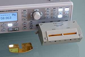
Handheld LCR meters typically have selectable test frequencies of 100 Hz, 120 Hz, 1 kHz, 10 kHz, and 100 kHz for top end meters. The display resolution and measurement range capability will typically change with test frequency.
Benchtop LCR meters typically have selectable test frequencies of more than 100 kHz. They often include options to superimpose a DC voltage or current on the AC measuring signal. Lower end meters offer the possibility to externally supply these DC voltages or currents while higher end devices can supply them internally. In addition benchtop meters allow the usage of special fixtures to measure SMD components, air-core coils or transformers.
Bridge circuits
_(2).jpg)
Inductance, capacitance, resistance, and dissipation factor can also be measured by various bridge circuits. They involve adjusting variable calibrated elements until the signal at a detector becomes null, rather than measuring impedance and phase angle.
Early commercial LCR bridges used a variety of techniques involving the matching or "nulling" of two signals derived from a single source. The first signal was generated by applying the test signal to the unknown and the second signal was generated by using a combination of known-value R and C standards. The signals were summed through a detector (normally a panel meter with or without some level of amplification). When zero current was noted by changing the value of the standards and looking for a "null" in the panel meter, it could be assumed that the current magnitude through the unknown was equal to that of the standard and that the phase was exactly the reverse (180 degrees apart). The combination of standards selected could be arranged to read out C and DF directly which was the precise value of the unknown. An example of this is the GenRad/IET Labs Model 1620 and 1621 Capacitance Bridges.
See also
External links
- "LCR Primer", IET Labs Inc., April 2012.