Lecher lines
In electronics, a Lecher line or Lecher wires is a pair of parallel wires or rods that were used to measure the wavelength of radio waves, mainly at UHF and microwave frequencies.[1][2] They form a short length of balanced transmission line (a resonant stub). When attached to a source of radio-frequency power such as a radio transmitter, the radio waves form standing waves along their length. By sliding a conductive bar that bridges the two wires along their length, the length of the waves can be physically measured. Austrian physicist Ernst Lecher, improving on techniques used by Oliver Lodge[3] and Heinrich Hertz,[4] developed this method of measuring wavelength around 1888.[5][6][7] Lecher lines were used as frequency measuring devices until frequency counters became available after World War 2. They were also used as components, often called "resonant stubs", in UHF and microwave radio equipment such as transmitters, radar sets, and television sets, serving as tank circuits, filters, and impedance-matching devices.[8] They are used at frequencies between HF/VHF, where lumped components are used, and UHF/SHF, where resonant cavities are more practical.
Wavelength measurement
A Lecher line is a pair of parallel uninsulated wires or rods held a precise distance apart. The separation is not critical but should be a small fraction of the wavelength; it ranges from less than a centimeter to over 10 cm. The length of the wires depends on the wavelength involved; lines used for measurement are generally several wavelengths long. The uniform spacing of the wires makes them a transmission line, conducting radio waves at a constant speed very close to the speed of light. One end of the rods is connected to the source of RF power, such as the output of a radio transmitter. At the other end the rods are connected together with a conductive bar between them. This short circuiting termination reflects the waves. The waves reflected from the short-circuited end interfere with the outgoing waves, creating a sinusoidal standing wave of voltage and current on the line. The voltage goes to zero at nodes located at multiples of half a wavelength from the end, with maxima called antinodes located midway between the nodes.[9] Therefore the wavelength λ can be determined by finding the location of two successive nodes (or antinodes) and measuring the distance between them, and multiplying by two. The frequency f of the waves can be calculated from the wavelength and the speed of the waves, which is the speed of light c:

The nodes are much sharper than the antinodes, because the change of voltage with distance along the line is maximum at the nodes, so they are used.
Finding the nodes
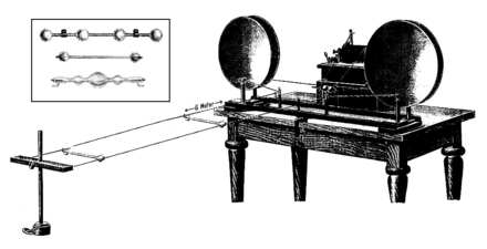
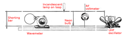
Two methods are employed to find the nodes.[9] One is to use some type of voltage indicator, such as an RF voltmeter or light bulb, attached to a pair of contacts that slide up and down the wires.[10][9] When the bulb reaches a node, the voltage between the wires goes to zero, so the bulb goes out. If the indicator has too low an impedance it will disturb the standing wave on the line, so a high impedance indicator must be used; a regular incandescent bulb has too low a resistance. Lecher and early researchers used long thin Geissler tubes, laying the glass tube directly across the line. The high voltage of early transmitters excited a glow discharge in the gas. In modern times small neon bulbs are often used. One problem with using glow discharge bulbs is their high striking voltage makes it difficult to localize the exact voltage minimum. In precision wavemeters an RF voltmeter is used.
The other method used to find the nodes is to slide the terminating shorting bar up and down the line, and measure the current flowing into the line with an RF ammeter in the feeder line.[9] The current on the Lecher line, like the voltage, forms a standing wave with nodes (points of minimum current) every half wavelength. So the line presents an impedance to the applied power which varies with its length; when a current node is located at the entrance to the line, the current drawn from the source, measured by the ammeter, will be minimum. The shorting bar is slid down the line and the position of two successive current minima is noted, the distance between them is half a wavelength.
With care, Lecher lines can measure frequency to an accuracy of 0.1%.[1]
Construction

A major attraction of Lecher lines was they were a way to measure frequency without complicated electronics, and could be improvised from simple materials found in a typical shop. Lecher line wavemeters are usually built on a frame which holds the conductors rigid and horizontal, with a track that the shorting bar or indicator rides on, and a built-in measuring scale so the distance between nodes can be read out. The frame must be made of a nonconductive material like wood, because any conducting objects near the line can disturb the standing wave pattern. The RF current is usually coupled into the line through a single turn loop of wire at one end, which can be held near a transmitter's tank coil.
A simpler design is a "U"-shaped metal bar, marked with graduations, with a sliding shorting bar. In operation, the U end acts as a coupling link and is held near the transmitter's tank coil, and the shorting bar is slid out along the arms until the transmitter's plate current dips, indicating the first node has been reached. Then the distance from the end of the link to the shorting bar is a half-wavelength. The shorting bar should always be slid out, away from the link end, not in, to avoid converging on a higher order node by mistake.
In many ways Lecher lines are an electrical version of the Kundt's tube experiment which is used to measure the wavelength of sound waves.
Measuring the speed of light
If the frequency f of the radio waves is independently known, the wavelength λ measured on a Lecher line can be used to calculate the speed of the waves, c, which is approximately equal to the speed of light:

In 1891, French physicist Prosper-René Blondlot made the first[11] measurement of the speed of radio waves, using this method.[12][13] He used 13 different frequencies between 10 and 30 MHz and obtained an average value of 297,600 km/s, which is within 1% of the current value for the speed of light.[11] Other researchers repeated the experiment with greater accuracy. This was an important confirmation of James Clerk Maxwell's theory that light was an electromagnetic wave like radio waves.
Other applications

Short lengths of Lecher line are often used as high Q resonant circuits, termed resonant stubs. For example, a quarter wavelength (λ/4) shorted Lecher line acts like a parallel resonant circuit, appearing as a high impedance at its resonant frequency and low impedance at other frequencies. They are used because at UHF frequencies the value of inductors and capacitors needed for 'lumped component' tuned circuits becomes extremely low, making them difficult to fabricate and sensitive to parasitic capacitance and inductance. One difference between them is that transmission line stubs like Lecher lines also resonate at odd-number multiples of their fundamental resonant frequency, while lumped LC circuits just have one resonant frequency.
Power amplifier tank circuits
Lecher line circuits can be used for the tank circuits of UHF power amplifiers.[14] For instance, the twin tetrode (QQV03-20) 432 MHz amplifier described by G.R Jessop[15] uses a Lecher line anode tank.
Television tuners
Quarter-wave Lecher lines are used for the tuned circuits in the RF amplifier and local oscillator portions of modern television sets. The tuning necessary to select different stations is done by varactor diodes across the Lecher line.[16]
Characteristic impedance of Lecher line
The separation between the Lecher bars does not affect the position of the standing waves on the line, but it does determine the characteristic impedance, which can be important for matching the line to the source of the radio frequency energy for efficient power transfer. For two parallel cylindrical conductors of diameter d and spacing D,

For parallel wires the formula for capacitance is
- l, length
- C, capacitance per meter

Hence as


Commercially available 300 and 450 ohm twin lead balanced ribbon feeder can be used as a fixed length Lecher line (resonant stub).
References
- 1 2 Endall, Robert (September 1946). "Frequency measurement at UHF" (PDF). Radio News. New York: Ziff-Davis Publishing. 36 (3): 52, 94–96. Retrieved March 24, 2014.
- ↑ Graf, Rudolph F. (1999). Modern Dictionary of Electronics. Newnes. p. 419. ISBN 0-7506-9866-7.
- ↑ Lodge, Oliver (1907). Modern Views of Electricity, 3rd Ed. London: MacMillan and Co. p. 235.
- ↑ Hertz, Heinrich (1891). "Theory of Stationary Waves on Wires". Wiedemann Annalen. 8: 407.
- ↑ Fleming, John Ambrose (1908). The Principles of Electric Wave Telegraphy. London: Longmans, Green & Co. pp. 264–270.
- ↑ E. Lecher (1888) "Eine studie uber electrische Resonanzerscheinungen" (Study of Electrical Resonance Phenomena), Wiedemann Annalen, Vol. 41, p. 850, cited in Fleming, 1908.
- ↑ "Electric Waves". Encyclopaedia Britannica, 11th Ed. 9. Cambridge Press. 1910. p. 207.
- ↑ Basu, Dipak (2001). Dictionary of Pure and Applied Physics. CRC Press. p. 206. ISBN 0-8493-2890-X.
- 1 2 3 4 Barr, D. L. (July 1932). "Demonstrating Short Waves" (PDF). Short Wave Craft. New York: Popular Book Corp. 3 (3): 153. Retrieved March 23, 2014.
- ↑ Franklin, William Suddards (1909). Electric Waves: An advanced treatise on alternating-current theory. New York: MacMillan. pp. 125–129.
- 1 2 "René Blondlot's Parallel Wires and Standing Waves". The Speed of Light. New Jersey Society for Amateur Scientists. 2002. Retrieved 2008-12-25., credited to K. D. Froome and L. Essen, "The Velocity of Light and Radio Waves", Academic Press, 1969
- ↑ "Length of Electric Waves". The Electrical Engineer. London: The Electrical Engineer, Ltd. 8: 482. November 20, 1891. Retrieved 2008-12-25.
- ↑ Deaton, Jennifer; Tina Patrick; revised by David Askey (2002). "History of the Speed of Light" (PDF). Junior Lab. Physics Dept. Univ. of Oklahoma. Retrieved 2008-12-25. Cite uses deprecated parameter
|coauthors=(help), p.15 - ↑ Gupta, K. C. (2003). Microwaves. New Age Publishers. pp. 36–37. ISBN 0-85226-346-5.
- ↑ G.R. Jessop, VHF UHF manual, RSGB, Potters Bar, 1983, ISBN 0-900612-92-4
- ↑ Ibrahim, K. F.; Eugene Trundle (2007). Newnes Guide to Television and Video Technology. Newnes. pp. 224–225. ISBN 0-7506-8165-9.
See also
External links
- "Index to Physics Demonstrations; Lecher wires". Physics Demonstrations, The University of Minnesota. 1997-06-16.
- "E-82. Electromagnetic Radiation; Demonstration Short-wave apparatus". Electricity/Magnetism, Lecture Demonstrations. Purdue University.
- M B Allenson, A R Piercy and K N R Taylor "An improved Lecher wire experiment". 1973 Phys. Educ. 8 47-49. doi 10.1088/0031-9120/8/1/002.
- F. C. Blake and B. H. Jackson, "The Relative Intensity of the Harmonics of a Lecher System (Experimental)". The Ohio Journal of Science. *PDF)
- F. C. Blake, "The Relative Intensity of the Harmonics of a Lecher System (Theoretical)". Physical Lab, Ohio State University. (PDF)