Metropolitan-Vickers F.2
| F.2/Beryl | |
|---|---|
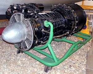 | |
| Beryl engine preserved at Solent Sky Museum | |
| Type | Turbojet |
| Manufacturer | Metropolitan-Vickers |
| First run | 1941 |
| Major applications | Saunders-Roe SR.A/1 |
|
| |
The Metropolitan-Vickers F.2 was an early turbojet engine and the first British design to be based on an axial-flow compressor. It was an extremely advanced design,[1] using a nine-stage axial compressor, annular combustor, and a two-stage turbine. It first powered a Gloster Meteor in November 1943, outperforming similar models from Power Jets.
In spite of this excellent start, it was considered unreliable and never saw use during the war. In the post-war era a number of engines had much higher performance, and interest in the F.2 waned. The potential of the engine and the investment did not go to waste, however, the design was passed from Metropolitan-Vickers to Armstrong Siddeley when Metrovick left the gas turbine business. Armstrong Siddeley produced a larger version as the successful Sapphire.
Development
Alan Arnold Griffith published a seminal paper in 1926, An Aerodynamic Theory of Turbine Design, that for the first time clearly demonstrated that a gas turbine could be used as a practical, and even desirable, aircraft powerplant. The paper started by demonstrating that existing axial compressor designs were "flying stalled" due to their use of flat blades, and that dramatic improvements could be made by using aerofoil designs instead, improvements that made a gas turbine practical. It went on to outline a complete compressor and turbine design, using the extra exhaust power to drive a second turbine that would power a propeller. In today's terminology the design was a turboprop.
In order to prove the design, Griffith and several other engineers at the Royal Aircraft Establishment built a testbed example of the compressor in 1928 known as Anne, the machinery being built for them by Fraser and Chalmers. After Anne's successful testing they planned to follow this up with a complete engine known as Betty, or B.10.
In 1929 Frank Whittle's thesis on pure jet engines was published, and sent to Griffith for comment. After pointing out an error in Whittle's mathematics, he went on to deride the entire concept, saying that the centrifugal compressor Whittle used would be impractical for aircraft use due to its large frontal area, and that the use of the jet exhaust directly for power would be extremely inefficient. Whittle was distraught, but was convinced that he should patent the idea anyway. Five years later a group of investors persuaded him to start work on what would be the first working British jet engine.
Griffith continued development of his own concepts, eventually developing an advanced compressor design using two contra-rotating stages that improved efficiency. His partner, Hayne Constant, started discussions in 1937 with Manchester-based Metrovick, a maker of steam turbines, to produce the new machinery. Incidentally, Metrovick had recently merged with British Thomson-Houston, another turbine builder who were supporting Whittle's efforts. By 1939 this work had developed several improved versions of the Betty compressor design, which were incorporated into the new Freda.
In April 1939, Whittle gave a startling demonstration of his experimental engine, the WU, running it for 20 minutes at high power. This led to a rash of contracts to build a production quality design suitable for aircraft use. Metrovick's lead of design, David Smith, decided to end development of the turboprop concepts and focus on pure-jets instead. Development had just started when Whittle started building his W.1 design, planning to install one for flight in the Gloster E.28/39 the next year.
F.1
In July 1940 the RAE signed a contract with Metrovick to build a flight-quality pure-turbojet engine based on the Freda turbine. This emerged as the F.1 concept, which was built in several forms, with the first runnable engine starting on the testbed in late 1941. The design cleared its special-category flight-tests in 1942, and flew for the first time on 29 June 1943 in the open bomb bay of an Avro Lancaster. Compared to the centrifugal-flow Whittle designs, the F.1 was extremely advanced, using a nine-stage axial compressor, annular combustion chamber, and a two-stage turbine.[1]
F.2
Development of the F.2 turbojet progressed rapidly, and the engine ran for the first time in November 1941. By this point there were a number of engines in development based on the Whittle concept, but the F.2 looked considerably more capable than any of them. Flyable versions, the F.2/1, received its test rating in 1942 and were flown on an Avro Lancaster test-bed (the first prototype Lancaster, s/n BT308) on 29 June 1943, mounted in the rear fuselage. Production quality versions were tested on the F.9/40M (Gloster Meteor) s/n DG204/G which made its first flight on 13 November 1943. These were installed in underslung nacelles, in a manner similar to the mounting of the engines of the Messerschmitt Me 262.[1]
As expected, the engines were more powerful than the Whittle design, first delivering 1,800 lbf (8 kN) but soon scaling up to well over 2,000 lbf (8.9 kN). Around this time, the Whittle W.2B was developing 1,600 lbf (7.11 kN). However, the F.2 engine suffered from a number of problems that cast doubts on its reliability. These were primarily due to hot spots building up on the turbine bearing and combustion chamber. The latter, in turn, caused warping and fractures of the turbine inlet nozzles.
F.2/2
To address these problems, in August 1942 a minor redesign delivered the F.2/2, which changed the turbine material from Rex 75 to Nimonic 75, and lengthened the combustion chamber by 6 inches (150 mm). Thrust was improved to 2,400 lbf (11,000 N) static, but the problems with overheating remained.
F.2/3
Another attempt to solve the overheating problems resulted in the more highly modified F.2/3 during 1943. This version replaced the original annular combustion chamber with can-type burners like those on the Whittle designs. This appears to have solved the problems, raising the thrust to 2,700 lbf (12,000 N) in the process. However, by this time it was decided to move on to a much more powerful version of the engine.
F.2/4 Beryl
Development of the F.2 continued on a version using a ten-stage compressor for additional airflow driven by a single stage turbine.[1] The new F.2/4 - the Beryl - initially developed 3,250 lbf (14.45 kN) and was test flown in Avro Lancaster Mk.II s/n LL735 before being installed in the Saunders-Roe SR.A/1 flying boat fighter. Thrust had already improved to 3,850 lbf (17.1 kN) for the third prototype, and eventually settled at 4,000 lbf (17.8 kN).
In comparison, the contemporary Derwent developed only 2,450 pounds-force (10,900 N) in its ultimate form; making the Beryl one of the most powerful engines of the era. Development of the SR.A/1 ended in 1947, ending development of the Beryl along with it. Nevertheless, a Beryl from the SR.A/1 prototype was removed and used by Donald Campbell for early runs in his famous 1955 Bluebird K7 hydroplane in which he set seven water speed records between 1955 and 1964.
F.3
In 1942 MV started work on thrust augmentation. The resulting Metropolitan-Vickers F.3 was the first British turbofan engine to be designed, built and tested. Indeed, it could be said that the F.3 was also the very first 3-shaft jet engine to be built, although the configuration was completely different from that of the much later Rolls-Royce RB211 turbofan series, since the fan was located at the rear of the engine, not unlike that of the General Electric CJ805-23. Using a stock F.2/2, MV added a separate module to the rear of the engine (directly behind the HP turbine) which comprised contra-rotating LP turbines attached to two contra-rotating fans.[2] Apart from the first stage nozzle guide vanes, the LP turbine was completely statorless, with four consecutive rotor stages. Rotors 1 and 3 drove the front fan clockwise (viewed from front), whereas the rear fan was driven anticlockwise by rotors 2 and 4. Although the front fan had inlet guide vanes, there were no vanes between the contra-rotating fan rotors or, downstream, any exit guide vanes. The core and bypass streams exhausted through separate coaxial propelling nozzles.
The project was generally successful, raising static thrust from around 2,400 lbf (11,000 N) to 4,000 lbf (18 kN). More importantly, specific fuel consumption fell from 1.05 to 0.65 lb/(lbf·h) (30 to 18 g/(kN·s)), which was the true aim of the project. The weight increase for all the extra turbomachinery and ducting was significant, however. A bonus was a marked decrease in noise levels which resulted from the slower, cold air from the fan mixing with the fast, hot exhaust from the gas generator.
Although the F.3 progressed nicely, development was curtailed by the pressures of war. When the war ended the F.2/2 was no longer current, so some of the ideas were applied to the more up-to-date F.2/4 to produce the Metropolitan-Vickers F.5 propfan.
F.5
Following on where the F.3 left off, the F.5 was a version of the F.2/4 with an open rotor (unducted) thrust augmenter added to the end of the jet pipe, somewhat remote from the HP turbine The 5 ft 6 in diameter fixed pitch propellers, which contra-rotated, were driven by a 4-stage statorless LP turbine unit, similar to that of the F.3. Static thrust increased from the 3500lbf of the F.2/2 to in excess of 4,710 lbf (21,000 N), with a corresponding reduction in specific fuel consumption. Relative to the parent turbojet, the weight increase for this prop fan configuration was about 26%, compared to 53% for the F.3 turbofan.[3] Development was cancelled when they sold their gas turbine business to Armstrong Siddeley in 1946.
F.9 Sapphire
Development of the F.2 ended in 1944. Development of the basic concept continued, however, eventually leading to the considerably larger F.9 Sapphire. However, in 1947, Metrovick left jet engine production and their design team moved to Armstrong Siddeley. The Sapphire matured into a successful design, initially besting the power of its Rolls-Royce contemporary, the Avon. Design features of the Metrovick line were worked into Armstrong Siddeley's own line of axial compressor turboprops, although Armstrong Siddeley dropped Metrovick's use of gemstone names for their engines in favour of continuing with animal names, in particular snakes.
An example of the prototype engine can be found in the Science Museum Flight Gallery in London.
Specifications (F.2/2)
Data from [4]
General characteristics
- Type: Axial flow turbojet
- Length: 159 in (4,038.6 mm)
- Diameter: 34.9 in (886.5 mm)
- Dry weight: ~1,500 lb (680.4 kg)
Components
- Compressor: 9-stage axial flow compressor
- Combustors: 1x Annular stainless steel combustion chamber
- Turbine: 2-stage axial flow turbine
- Fuel type: Kerosene (R.D.E. / F / KER)
Performance
- Maximum thrust: 2,400 lbf (10.68 kN) at sea level static, take-off
- Overall pressure ratio: 3.5:1
- Air mass flow: ~50.23lb/s (~22.78kg/s)
- Turbine inlet temperature: 1,382 °F (750 °C)
- Specific fuel consumption: 1.07 lb/(lbf·h) (30 g/(kN·s))
- Thrust-to-weight ratio: ~1.6:1
See also
- Comparable engines
- Related lists
References
- 1 2 3 4 "Armstrong Siddeley Sapphire", Flight, 6 January 1956, pp. 17-22.
- ↑ "Metrovick F3 Cutaway - Pictures & Photos on FlightGlobal Airspace". Flightglobal.com. 2007-11-07. Retrieved 2012-03-05.
- ↑ "Metrovick F.5", Flight, 2 January 1947, p. 18.
- ↑ Wilkinson, Paul H. (1946). Aircraft Engines of the world 1946. London: Sir Isaac Pitman & Sons. pp. 288–289.
External links
- "Metro-Vick Gas Turbine" a 1946 Flight article
- "Metrovick F.5" a 1947 Flight article on the F.5 propfan