N connector
|
Type N connector (male) | |||
| Type | RF coaxial connector | ||
|---|---|---|---|
| Production history | |||
| Designer | Paul Neill | ||
| Designed | 1940s | ||
| General specifications | |||
| Diameter |
Male: 0.800 in (2.03 cm) Female: 0.620 in (1.57 cm)[1] (outer, typical) | ||
| Cable | Coaxial | ||
| Passband | 0-11 GHz, often up to 18 GHz | ||
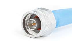
The N connector (in full, Type N connector) is a threaded, weatherproof, medium-size RF connector used to join coaxial cables. It was one of the first connectors capable of carrying microwave-frequency signals, and was invented in the 1940s by Paul Neill of Bell Labs, after whom the connector is named.[2]
Design
Originally, the connector was designed to carry signals at frequencies up to 1 GHz in military applications, but today's common Type N easily handles frequencies up to 11 GHz. More recent precision enhancements to the design by Julius Botka at Hewlett Packard have pushed this to 18 GHz. The male connector is hand-tightened (though versions with a hex nut are also available) and has an air gap between the center and outer conductors. The coupling has a 5/8-24 thread. The center coaxial contacts are identical to TNC and BNC connectors. Amphenol [2] suggests tightening to a torque of 15 inch-pounds (1.7 N·m), while Andrew Corporation suggest 20 inch-pounds (2.3 N·m) for their hex nut variant. As torque limit depends only on thread quality and cleanliness, whereas the main operational requirement is good RF contact without significant steps or gaps, these values should be seen as indicative rather than critical.
Power rating
The peak power rating of an N connector is determined by voltage breakdown/ionisation of the air near the center pin. The average power rating is determined by overheating of the centre contact due to resistive insertion loss, and thus is a function of frequency. Typical makers' curves for a new clean connector with a perfect load (VSWR=1.0) give limits of ≈5000 W at 20 MHz and ≈500 W at 2 GHz.[3] This square root frequency derating law is expected from the skin depth decreasing with frequency. At lower frequencies the same maker recommends an upper bound of ≈1000 V RMS. To achieve reliable operation in practice over an extended period, a safety factor of 5 or more is not uncommon, particularly when generic parts may be substituted, or the operating environment is likely to lead to eventual tarnishing of the contacts.
Impedance options
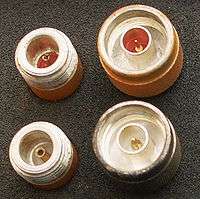
The N connector follows the MIL-STD-348 standard, defined by the US military, and comes in 50 and 75 ohm versions. The 50 ohm version is widely used in the infrastructure of land mobile, wireless data, paging and cellular systems. The 75 ohm version is primarily used in the infrastructure of cable television systems. Connecting these two different types of connectors to each other can lead to damage, and/or intermittent operation due to the difference in diameter of the center pin.[4]
Unfortunately, many type N connectors are not labeled, and it can be difficult to prevent this situation in a mixed impedance environment. The situation is further complicated by some makers of 75 ohm sockets designing them with enough spring yield to accept the larger 50 ohm pin without irreversible damage, while others clearly do not, and expect users to segregate their connectors and adaptors. In general a 50 ohm socket is not damaged by a 75 ohm pin, but the loose fit means the contact quality is not guaranteed; this can cause poor or intermittent operation, with the thin 75 ohm male pin only barely mating with the larger 50 ohm socket in the female.
The 50 ohm type N connector is favored by enthusiasts who create their own Wireless LAN antenna systems, which run at 2.4 GHz or 5 GHz. The Cantenna is one such design. The enthusiasts have settled on using the N connector as a standard connection for homebrew antennas. By using a cable with an N connector one can easily interchange homebrew antennas. 50 Ω N connectors are also commonly used on amateur radio devices (e.g., transceivers) operating in UHF bands.
Variations
SnapN
SnapN was originally designed by Rosenberger Hochfrequenztechnik in 2006 and is a quick locking replacement for the threaded interface of the widely applied Type N connector. Though part of the Quick Lock Formula Alliance (QLF), engineers at Rosenberger independently designed the SnapN in order to correct the performance problems of QLF’s version of the quick lock N connector, QN. This design achieves better electronic performance because, unlike the QN, this new version maintains the basic structural parameters of the original Type N in which the inner dimensions of the outer conductor are 7.00 mm, and the inner conductor’s outer dimensions are 3.04 mm. A male N-connector can plug into an female SnapN.[5]
HN
The HN connector is slightly larger (3/4"-20 thread) and is designed for high-voltage applications.[6]
See also
- RF connector
- SMA connector, SMB connector, SMC connector
- UHF connector (aka PL-259 Connector)
- Optical fiber connector
References
- ↑ Radiall R191381000 datasheet
- 1 2 Amphenol, N type datasheet (PDF)
- ↑ RF Coaxial Connectors General Catalogue. Huber+Suhner. 2007/2008. pp. 275–276. Check date values in:
|date=(help) - ↑ Golio, Mike (2008). The RF and Microwave Handbook, Second Edition. CRC. pp. 8–7. ISBN 978-0-8493-7217-9.
- ↑ https://www.rosenberger.com/en/products/communication/quicklock.php
- ↑ http://www.amphenolrf.com/connectors/hn-type.html
^ N type connectors from Cmpter Electronics