Natural-gas processing
Natural-gas processing is a complex industrial process designed to clean raw natural gas by separating impurities and various non-methane hydrocarbons and fluids to produce what is known as pipeline quality dry natural gas.[1]
Natural-gas processing begins at the well head. The composition of the raw natural gas extracted from producing wells depends on the type, depth, and location of the underground deposit and the geology of the area. Oil and natural gas are often found together in the same reservoir. The natural gas produced from oil wells is generally classified as associated-dissolved, meaning that the natural gas is associated with or dissolved in crude oil. Natural gas production absent any association with crude oil is classified as “non-associated.” In 2009, 89 percent of U.S. wellhead production of natural gas was non-associated.[2]
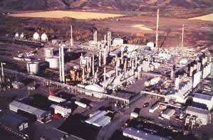
Natural-gas processing plants purify raw natural gas by removing common contaminants such as water, carbon dioxide (CO2) and hydrogen sulfide (H2S). Some of the substances which contaminate natural gas have economic value and are further processed or sold. A fully operational plant delivers pipeline-quality dry natural gas that can be used as fuel by residential, commercial and industrial consumers.
Types of raw-natural-gas wells
Raw natural gas comes primarily from any one of three types of wells: crude oil wells, gas wells, and condensate wells.
Natural gas that comes from crude oil wells is typically called associated gas. This gas can have existed as a gas cap above the crude oil in the underground formation, or could have been dissolved in the crude oil.
Natural gas from gas wells and from condensate wells, in which there is little or no crude oil, is called non-associated gas. Gas wells typically produce only raw natural gas, while condensate wells produce raw natural gas along with other low molecular weight hydrocarbons. Those that are liquid at ambient conditions (i.e., pentane and heavier) are called natural gas condensate (sometimes also called natural gasoline or simply condensate).
Natural gas is called sweet gas when relatively free of hydrogen sulfide; gas that does contain hydrogen sulfide is called sour gas. Natural gas, or any other gas mixture, containing significant quantities of hydrogen sulfide, carbon dioxide or similar acidic gases, is called acid gas
Raw natural gas can also come from methane deposits in the pores of coal seams, and especially in a more concentrated state of adsorption onto the surface of the coal itself. Such gas is referred to as coalbed gas or coalbed methane (coal seam gas in Australia). Coalbed gas has become an important source of energy in recent decades.
Contaminants in raw natural gas
Raw natural gas typically consists primarily of methane (CH4), the shortest and lightest hydrocarbon molecule. It also contains varying amounts of:
- Heavier gaseous hydrocarbons: ethane (C2H6), propane (C3H8), normal butane (n-C4H10), isobutane (i-C4H10), pentanes and even higher molecular weight hydrocarbons. When processed and purified into finished by-products, all of these are collectively referred to as Natural Gas Liquids or NGL.
- Acid gases: carbon dioxide (CO2), hydrogen sulfide (H2S) and mercaptans such as methanethiol (CH3SH) and ethanethiol (C2H5SH).
- Other gases: nitrogen (N2) and helium (He).
- Water: water vapor and liquid water. Also dissolved salts and dissolved gases (acids).
- Liquid hydrocarbons: perhaps some natural-gas condensate (also referred to as casinghead gasoline or natural gasoline) and/or crude oil.
- Mercury: very small amounts of mercury primarily in elemental form, but chlorides and other species are possibly present.[3]
- Naturally occurring radioactive material (NORM): natural gas may contain radon, and the produced water may contain dissolved traces of radium, which can accumulate within piping and processing equipment. This can render piping and equipment radioactive over time.
The raw natural gas must be purified to meet the quality standards specified by the major pipeline transmission and distribution companies. Those quality standards vary from pipeline to pipeline and are usually a function of a pipeline system's design and the markets that it serves. In general, the standards specify that the natural gas:
- Be within a specific range of heating value (caloric value). For example, in the United States, it should be about 1035 ± 5% BTU per cubic foot of gas at 1 atmosphere and 60°F (41 MJ ± 5% per cubic metre of gas at 1 atmosphere and 15.6°C).
- Be delivered at or above a specified hydrocarbon dew point temperature (below which some of the hydrocarbons in the gas might condense at pipeline pressure forming liquid slugs that could damage the pipeline).
- Dew-point adjustment serves the reduction of the concentration of water and heavy hydrocarbons in natural gas to such an extent that no condensation occurs during the ensuing transport in the pipelines
- Be free of particulate solids and liquid water to prevent erosion, corrosion or other damage to the pipeline.
- Be dehydrated of water vapor sufficiently to prevent the formation of methane hydrates within the gas processing plant or subsequently within the sales gas transmission pipeline. A typical water content specification in the U.S. is that gas must contain no more than seven pounds of water per million standard cubic feet (MMSCF) of gas.[4][5]
- Contain no more than trace amounts of components such as hydrogen sulfide, carbon dioxide, mercaptans, and nitrogen. The most common specification for hydrogen sulfide content is 0.25 grain H2S per 100 cubic feet of gas, or approximately 4 ppm. Specifications for CO2 typically limit the content to no more than two or three percent.
- Maintain mercury at less than detectable limits (approximately 0.001 ppb by volume) primarily to avoid damaging equipment in the gas processing plant or the pipeline transmission system from mercury amalgamation and embrittlement of aluminum and other metals.[3][6][7]
Description of a natural-gas processing plant
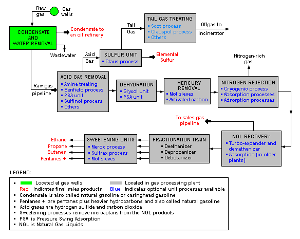
There are a great many ways in which to configure the various unit processes used in the processing of raw natural gas. The block flow diagram below is a generalized, typical configuration for the processing of raw natural gas from non-associated gas wells. It shows how raw natural gas is processed into sales gas pipelined to the end user markets.[8][9][10][11][12] It also shows how processing of the raw natural gas yields these byproducts:
- Natural-gas condensate
- Sulfur
- Ethane
- Natural-gas liquids (NGL): propane, butanes and C5+ (which is the commonly used term for pentanes plus higher molecular weight hydrocarbons)
Raw natural gas is commonly collected from a group of adjacent wells and is first processed at that collection point for removal of free liquid water and natural gas condensate. The condensate is usually then transported to an oil refinery and the water is disposed of as wastewater.
The raw gas is then pipelined to a gas processing plant where the initial purification is usually the removal of acid gases (hydrogen sulfide and carbon dioxide). There are many processes that are available for that purpose as shown in the flow diagram, but amine treating is the process that was historically used. However, due to a range of performance and environmental constraints of the amine process, a newer technology based on the use of polymeric membranes to separate the carbon dioxide and hydrogen sulfide from the natural gas stream has gained increasing acceptance. Membranes are attractive since no reagents are consumed.[13]
The acid gases, if present, are removed by membrane or amine treating can then be routed into a sulfur recovery unit which converts the hydrogen sulfide in the acid gas into either elemental sulfur or sulfuric acid. Of the processes available for these conversions, the Claus process is by far the most well known for recovering elemental sulfur, whereas the conventional Contact process and the WSA (Wet sulfuric acid process) are the most used technologies for recovering sulfuric acid.
The residual gas from the Claus process is commonly called tail gas and that gas is then processed in a tail gas treating unit (TGTU) to recover and recycle residual sulfur-containing compounds back into the Claus unit. Again, as shown in the flow diagram, there are a number of processes available for treating the Claus unit tail gas and for that purpose a WSA process is also very suitable since it can work autothermally on tail gases.
The next step in the gas processing plant is to remove water vapor from the gas using either the regenerable absorption in liquid triethylene glycol (TEG),[5] commonly referred to as glycol dehydration, deliquescent chloride desiccants, and or a Pressure Swing Adsorption (PSA) unit which is regenerable adsorption using a solid adsorbent.[14] Other newer processes like membranes may also be considered.
Mercury is then removed by using adsorption processes (as shown in the flow diagram) such as activated carbon or regenerable molecular sieves.[3]
Although not common, nitrogen is sometimes removed and rejected using one of the three processes indicated on the flow diagram:
- Cryogenic process (Nitrogen Rejection Unit),[15] using low temperature distillation. This process can be modified to also recover helium, if desired (see also industrial gas).
- Absorption process,[16] using lean oil or a special solvent[17] as the absorbent.
- Adsorption process, using activated carbon or molecular sieves as the adsorbent. This process may have limited applicability because it is said to incur the loss of butanes and heavier hydrocarbons.
The next step is to recover the natural gas liquids (NGL) for which most large, modern gas processing plants use another cryogenic low temperature distillation process involving expansion of the gas through a turbo-expander followed by distillation in a demethanizing fractionating column.[18][19] Some gas processing plants use lean oil absorption process[16] rather than the cryogenic turbo-expander process.
The residue gas from the NGL recovery section is the final, purified sales gas which is pipelined to the end-user markets.
The recovered NGL stream is sometimes processed through a fractionation train consisting of three distillation towers in series: a deethanizer, a depropanizer and a debutanizer. The overhead product from the deethanizer is ethane and the bottoms are fed to the depropanizer. The overhead product from the depropanizer is propane and the bottoms are fed to the debutanizer. The overhead product from the debutanizer is a mixture of normal and iso-butane, and the bottoms product is a C5+ mixture. The recovered streams of propane, butanes and C5+ may be "sweetened" in a Merox process unit to convert undesirable mercaptans into disulfides and, along with the recovered ethane, are the final NGL by-products from the gas processing plant. Currently, most cryogenic plants do not include fractionation for economic reasons, and the NGL stream is instead transported as a mixed product to standalone fractionation complexes located near refineries or chemical plants that use the components for feedstock. In case laying pipeline is not possible for geographical reason,or the distance between source and consumer exceed 3000 km, natural gas is then transported by ship as LNG (liquefied natural gas) and again converted into its gaseous state in the vicinity of the consumer.
Helium recovery
If the gas contains significant helium content, the helium may be recovered by fractional distillation. Natural gas may contain as much as 7% helium, and is the commercial source of the noble gas.[20] For instance, the Hugoton Gas Field in Kansas and Oklahoma in the United States contains concentrations of helium from 0.3% to 1.9%, which is separated out as a valuable byproduct.[21]
Consumption
Natural gas consumption patterns, across nations, vary based on access. Countries with large reserves tend to handle the raw-material natural gas more generously, while countries with scarce or lacking resources tend to be more economical. Despite the considerable findings, the predicted availability of the natural-gas reserves has hardly changed.
Applications of natural gas
- Fuel for industrial heating and desiccation process
- Fuel for the operation of public and industrial power stations
- Household fuel for cooking, heating and providing hot water
- Fuel for environmentally friendly compressed or liquid natural gas vehicles
- Raw material for chemical synthesis
- Raw material for large-scale fuel production using gas-to-liquid (GTL) process (e.g. to produce sulphur-and aromatic-free diesel with low-emission combustion)
See also
- Natural gas prices
- Oil refinery
- List of natural gas and oil production accidents in the United States
References
- ↑ Fact Sheet: Natural Gas Processing Plants
- ↑ https://mitei.mit.edu/system/files/NaturalGas_Chapter2_Supply.pdf
- 1 2 3 "Mercury Removal from Natural Gas and Liquids" (PDF). UOP LLC. Archived from the original (PDF) on 2011-01-01.
- ↑ Dehydration of Natural Gas by Prof. Jon Steiner Gudmundsson, Norwegian University of Science and Technology
- 1 2 Glycol Dehydration (includes a flow diagram)
- ↑ Desulfurization of and Mercury Removal From Natural Gas by Bourke, M.J. and Mazzoni, A.F., Laurance Reid Gas Conditioning Conference, Norman, Oklahoma, March 1989.
- ↑ Using Gas Geochemistry to Assess Mercury Risk, OilTracers, 2006
- ↑ Natural Gas Processing: The Crucial Link Between Natural Gas Production and Its Transportation to Market
- ↑ Example Gas Plant
- ↑ From Purification to Liquefaction Gas Processing
- ↑ Feed-Gas Treatment Design for the Pearl GTL Project
- ↑ Benefits of integrating NGL extraction and LNG liquefaction
- ↑ Baker, R. W. "Future Directions of Membrane Gas Separation Technology" Ind. Eng. Chem. Res. 2002, volume 41, pages 1393-1411. doi:10.1021/ie0108088
- ↑ Molecular Sieves (includes a flow diagram of a PSA unit)
- ↑ Gas Processes 2002, Hydrocarbon Processing, pages 84–86, May 2002 (schematic flow diagrams and descriptions of the Nitrogen Rejection and Nitrogen Removal processes)
- 1 2 Market-Driven Evolution of Gas Processing Technologies for NGLs Advanced Extraction Technology Inc. website page
- ↑ AET Process Nitrogen Rejection Unit Advanced Extraction Technology Inc. website page
- ↑ Cryogenic Turbo-Expander Process Advanced Extraction Technology Inc. website page
- ↑ Gas Processes 2002, Hydrocarbon Processing, pages 83–84, May 2002 (schematic flow diagrams and descriptions of the NGL-Pro and NGL Recovery processes)
- ↑ Winter, Mark (2008). "Helium: the essentials". University of Sheffield. Retrieved 2008-07-14.
- ↑ Dwight E. Ward and Arthur P. Pierce (1973) "Helium" in United States Mineral Resources, US Geological Survey, Professional Paper 820, p.285-290.
External links
- Simulate natural gas processing using Aspen HYSYS
- Natural Gas Processing Principles and Technology (an extensive and detailed course text by Dr. A.H. Younger, University of Calgary, Alberta, Canada).
- Processing Natural Gas, Website of the Natural Gas Supply Association (NGSA).
- Natural Gas Processing (part of the US EPA's AP-42 publication)
- Natural Gas Processing Plants (a US Department of Transportation website)
- Gas Processors Association, Website of the Gas Processors Association (GPA) headquartered in Tulsa, Oklahoma, United States.
- Gas Processing Journal (Publisher: College of Engineering, University of Isfahan, Iran.)
Further reading
- Haring, H.W. (2008). Industrial Gases Processing. Weinheim, Germany: WILEY-VCH Verlag Gmbh & CO. KGaA
- Kohl, A., & Nielsen, R. (1997). Gas Purification. 5TH Edition. Houston, Texas: Gulf Publishing Company