Non-directional beacon

A non-directional (radio) beacon (NDB) is a radio transmitter at a known location, used as an aviation or marine navigational aid. As the name implies, the signal transmitted does not include inherent directional information, in contrast to other navigational aids such as low frequency radio range, VHF omnidirectional range (VOR) and TACAN. NDB signals follow the curvature of the Earth, so they can be received at much greater distances at lower altitudes, a major advantage over VOR. However, NDB signals are also affected more by atmospheric conditions, mountainous terrain, coastal refraction and electrical storms, particularly at long range.
Types of NDBs
NDBs used for aviation are standardised by ICAO Annex 10 which specifies that NDBs be operated on a frequency between 190 kHz and 1750 kHz,[1] although normally all NDBs in North America operate between 190 kHz and 535 kHz.[1] Each NDB is identified by a one, two, or three-letter Morse code callsign. In Canada, privately owned NDB identifiers consist of one letter and one number. North American NDBs are categorized by power output, with low power rated at less than 50 watts, medium from 50 W to 2,000 W and high being over 2,000 W.[2]
There are four types of non-directional beacons in the aeronautical navigation service:[3]
- En route NDBs, used to mark airways
- Approach NDBs
- Localizer beacons
- Locator beacons
The last two types are used in conjunction with an Instrument Landing System (ILS).
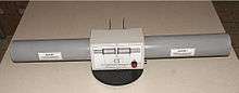
Automatic direction finder equipment
NDB navigation consists of two parts — the automatic direction finder (or ADF) equipment on the aircraft that detects an NDB's signal, and the NDB transmitter. The ADF can also locate transmitters in the standard AM medium wave broadcast band (530 kHz to 1700 kHz at 10 kHz increments in the Americas, 531 kHz to 1602 kHz at 9 kHz increments in the rest of the world).
ADF equipment determines the direction or bearing to the NDB station relative to the aircraft by using a combination of directional and non-directional antennae to sense the direction in which the combined signal is strongest. This bearing may be displayed on a relative bearing indicator (RBI). This display looks like a compass card with a needle superimposed, except that the card is fixed with the 0 degree position corresponding to the centreline of the aircraft. In order to track toward an NDB (with no wind) the aircraft is flown so that the needle points to the 0 degree position, the aircraft will then fly directly to the NDB. Similarly, the aircraft will track directly away from the NDB if the needle is maintained on the 180 degree mark. With a crosswind, the needle must be maintained to the left or right of the 0 or 180 position by an amount corresponding to the drift due to the crosswind. (Aircraft Heading +/- ADF needle degrees off nose or tail = Bearing to or from NDB station).
The formula to determine the compass heading to an NDB station (in a no wind situation) is to take the relative bearing between the aircraft and the station, and add the magnetic heading of the aircraft; if the total is greater than 360 degrees, then 360 must be subtracted. This gives the magnetic bearing that must be flown: (RB + MH)%360 = MB.
When tracking to or from an NDB, it is also usual that the aircraft track on a specific bearing. To do this it is necessary to correlate the RBI reading with the compass heading. Having determined the drift, the aircraft must be flown so that the compass heading is the required bearing adjusted for drift at the same time as the RBI reading is 0 or 180 adjusted for drift. An NDB may also be used to locate a position along the aircraft's current track (such as a radial path from a second NDB or a VOR). When the needle reaches an RBI reading corresponding to the required bearing then the aircraft is at the position. However, using a separate RBI and compass, this requires considerable mental calculation to determine the appropriate relative bearing.
To simplify this task, a compass card driven by the aircraft's magnetic compass is added to the RBI to form a "Radio Magnetic Indicator" (RMI). The ADF needle is then referenced immediately to the aircraft's magnetic heading, which reduces the necessity for mental calculation. Many RMIs used for aviation also allow the device to display information from a second radio tuned to a VOR station; the aircraft can then fly directly between VOR stations (so-called "Victor" routes) while using the NDBs to triangulate their position along the radial, without the need for the VOR station to have a collocated DME. This display, along with the "Omni Bearing Indicator" for VOR/ILS information, was one of the primary radionavigation instruments prior to the introduction of the Horizontal Situation Indicator and subsequent digital displays used in glass cockpits.
The principles of ADFs are not limited to NDB usage; such systems are also used to detect the locations of broadcast signals for many other purposes, such as finding emergency beacons.
Use of non-directional beacons
Airways
A bearing is a line passing through the station that points in a specific direction, such as 270 degrees (due West). NDB bearings provide a charted, consistent method for defining paths aircraft can fly. In this fashion, NDBs can, like VORs, define "airways" in the sky. Aircraft follow these pre-defined routes to complete a flight plan. Airways are numbered and standardized on charts; colored airways are used for low to medium frequency stations like the NDB and are charted in brown on sectional charts. Green and red airways are plotted east and west while amber and blue airways are plotted north and south. There are only two colored airways left in the continental United States. One is located off the coast of North Carolina and is called G13 or Green 13 and the other, B9 or Blue 9, is located in the Florida Keys.[4] Alaska is the only other state in the United States to make use of the colored airway systems.[5] Pilots follow these routes by tracking radials across various navigation stations, and turning at some. While most airways in the United States are based on VORs, NDB airways are common elsewhere, especially in the developing world and in lightly populated areas of developed countries, like the Canadian Arctic, since they can have a long range and are much less expensive to operate than VORs.
All standard airways are plotted on aeronautical charts, such as U.S. sectional charts, issued by the National Oceanographic and Atmospheric Administration (NOAA).
Fixes
NDBs have long been used by aircraft navigators, and previously mariners, to help obtain a fix of their geographic location on the surface of the Earth. Fixes are computed by extending lines through known navigational reference points until they intersect. For visual reference points, the angles of these lines can be determined by compass; the bearings of NDB radio signals are found using RDF equipment.
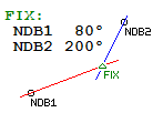
Plotting fixes in this manner allow crews to determine their position. This usage is important in situations where other navigational equipment, such as VORs with distance measuring equipment (DME), have failed. In marine navigation, NDBs may still be useful should GPS reception fail.
Determining distance from an NDB station
To determine the distance in relation to an NDB station in nautical miles, the pilot uses this simple method:
- Turns the aircraft so that the station is directly off one of the wingtips.
- Flies that heading, timing how long it takes to cross a specific number of NDB bearings.
- Uses the formula: Time to station = 60 x number of minutes flown / degrees of bearing change
- Uses the flight computer to calculate the distance the aircraft is from the station; time * speed = distance
NDB approaches
A runway equipped with NDB or VOR (or both) as the only navigation aid is called a non-precision approach runway; if it is equipped with ILS it is called a precision approach runway.
Instrument landing systems
NDBs are most commonly used as markers or "locators" for an instrument landing system (ILS) approach or standard approach. NDBs may designate the starting area for an ILS approach or a path to follow for a standard terminal arrival procedure, or STAR. In the United States, an NDB is often combined with the outer marker beacon in the ILS approach (called a locator outer marker, or LOM); in Canada, low-powered NDBs have replaced marker beacons entirely. Marker beacons on ILS approaches are now being phased out worldwide with DME ranges used instead to delineate the different segments of the approach. German Navy U-boats during World War II were equipped with a Telefunken Spez 2113S homing beacon. This transmitter could operate on 100 kHz to 1500 kHz with a power of 150 W. It was used to send the submarine's location to other submarines or aircraft, which were equipped with DF receivers and loop antennas.[6]
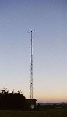
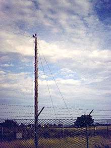
Antenna and signal characteristics
NDBs typically operate in the frequency range from 190 kHz to 535 kHz (although they are allocated frequencies from 190 to 1750 kHz) and transmit a carrier modulated by either 400 or 1020 Hz. NDBs can also be collocated with a DME in a similar installation for the ILS as the outer marker, only in this case, they function as the inner marker. NDB owners are mostly governmental agencies and airport authorities.
NDB radiators are vertically polarised. NDB antennas are usually too short for resonance at the frequency they operate – typically perhaps 20m length compared to a wavelength around 1000m. Therefore, they require a suitable matching network that may consist of an inductor and a capacitor to "tune" the antenna. Vertical NDB antennas may also have a 'top hat', which is an umbrella-like structure designed to add loading at the end and improve its radiating efficiency. Usually a ground plane or counterpoise is connected underneath the antenna.
Other information transmitted by an NDB
Apart from Morse Code Identity of either 400 Hz or 1020 Hz, the NDB may broadcast:
- Automatic Terminal Information Service or ATIS
- Automatic Weather Information Service, or AWIS, or, in an emergency i.e. Air-Ground-Air Communication failure, an Air Traffic Controller using a Press-To-Talk (PTT) function, may modulate the carrier with voice. The pilot uses their ADF receiver to hear instructions from the Tower.
- Automated Weather Observation System or AWOS
- Automated Surface Observation System or ASOS
- Meteorological Information Broadcast or VOLMET
- Transcribed Weather Broadcast or TWEB
- PIP monitoring. If an NDB has a problem, e.g. lower than normal power output, failure of mains power or standby transmitter is in operation, the NDB may be programmed to transmit an extra 'PIP' (a Morse dot), to alert pilots and others that the beacon may be unreliable for navigation.
Common adverse effects
Navigation using an ADF to track NDBs is subject to several common effects:
- Night effect: radio waves reflected back by the ionosphere can cause signal strength fluctuations 30 to 60 nautical miles (54 to 108 km) from the transmitter, especially just before sunrise and just after sunset (more common on frequencies above 350 kHz) Because the returning sky waves travel over a different path, they have a different phase from the ground wave. This has the effect of suppressing or displacing the aerial signal, in a random manner. The needle on the indicator will start wandering. The indication will be most erratic during twilight at dusk and dawn.
- Terrain effect: high terrain like mountains and cliffs can reflect radio waves, giving erroneous readings; magnetic deposits can also cause erroneous readings
- Thunderstorm effect: water droplets and ice crystals circulating within a storm cloud, generates wideband noise, this high power noise may affect the accuracy of the ADF bearing. Lightning, due to the high power output will cause the needle of the RMI/RBI to point for a moment to the bearing of the lightning.
- Shoreline effect: Radio waves speed up over water causing the wave front to bend away from its normal path and pull it towards the coast. Refraction is negligible at 90 to the coast but increases as the angle of incidence increases. The effect can be minimised by: flying higher and/or using NDB’s near the coast.
- Station interference: Due to congestion of stations in the LF and MF bands, the possibility of interference from stations on or near the same frequency exists. This will cause bearing errors. By day, the use of an NDB within the DOC will normally afford protection from interference. However, at night, one can expect interference even within the DOC because of skywave contamination from stations out of range by day. Therefore, positive identification of the NDB at night should always be carried out.
- Dip (bank) angle: during turns, the horizontal part of the loop aerial will no longer be horizontal and detect a signal. This causes displacement of the null in a way similar to the night effect giving an erroneous reading on the indicator which means that the pilot should not obtain a bearing unless the aircraft is wings level.
While pilots study these effects during initial training, trying to compensate for them in flight is very difficult; instead, pilots generally simply choose a heading that seems to average out any fluctuations.
Radio-navigation aids must keep a certain degree of accuracy, given by international standards, FAA, ICAO, etc.; to assure this is the case, Flight inspection organizations periodically check critical parameters with properly equipped aircraft to calibrate and certify NDB precision. The icao minimum accuracy for NDB's is ±5°
Monitoring NDBs
Besides their use in aircraft navigation, NDBs are also popular with long-distance radio enthusiasts ("DXers"). Because NDBs are generally low-power (usually 25 watts, some can be up to 5 kW), they normally cannot be heard over long distances, but favorable conditions in the ionosphere can allow NDB signals to travel much farther than normal. Because of this, radio DXers interested in picking up distant signals enjoy listening to faraway NDBs. Also, since the band allocated to NDBs is free of broadcast stations and their associated interference, and because most NDBs do little more than transmit their Morse Code callsign, they are very easy to identify, making NDB monitoring an active niche within the DXing hobby.
In North America, the NDB band is from 190 to 435 kHz and from 510 to 530 kHz. In Europe, there is a longwave broadcasting band from 150 to 280 kHz, so the European NDB band is from 280 kHz to 530 kHz with a gap between 495 and 505 kHz because 500 kHz was the international maritime distress (emergency) frequency.
The beacons that are between 510 kHz and 530 kHz can sometimes be heard on AM radios that can tune below the beginning of the Medium Wave(MW) broadcast band. Frequencies close to the MW band, like 515 kHz, may be within the receive bandwidth of some AM radios. However, reception of NDBs generally requires a radio receiver that can receive frequencies below 530 kHz (the longwave band). A NDB in Miramichi, New Brunswick once operated at 530 kHz as "F9" but had later moved to 520 kHz. Most so-called "shortwave" radios also include mediumwave and longwave, and they can usually receive all frequencies from 150 kHz to 30 MHz, which makes them ideal for listening to NDBs. Whilst this type of receiver is adequate for reception of local beacons, specialized techniques (receiver preselectors, noise limiters and filters) are required for the reception of very weak signals from remote beacons.[7]
The best time to hear NDBs that are very far away (i.e. that are "DX") is the last three hours before sunrise. Reception of NDBs is also usually best during the fall and winter because during the spring and summer, there is more atmospheric noise on the LF and MF bands.
See also
- Cardioid
- Direction finding
- Distance measuring equipment (DME)
- Electric beacon
- Global Positioning System (GPS)
- Instrument flight rules (IFR)
- Instrument landing system (ILS)
- Low-frequency radio range
- Satellite navigation
- Transponder landing system (TLS)
- VHF omnidirectional range (VOR)
References
- 1 2 "U.S. FAA Aeronautical Information Manual Chapter 1. Section 1. 1-1-2". Retrieved 2008-04-27.
- ↑ "ADF (Automatic Direction Finder)". Navigation Systems – Level 3. ALLSTAR Network. May 4, 2008. Retrieved 17 October 2010.
- ↑ Robert Connolly (February 2016). "Types of NDB". Radio User. 11 (2): 48–49. ISSN 1748-8117.
- ↑ Federal Aviation Administration. (2016). Minimum enroute ifr altitudes over particular routes and intersections (FAA Part 95 - Subchapter F). Washington, DC: Federal Aviation Administration.
- ↑ "FAA Aeronautical Information Manual, 5-3-4. Airways and Route Systems". Archived from the original on 2011-07-21.
- ↑ Robert Connolly (December 2010). "Beacon Updates and Frequencies to Try". Radio User. 5 (12): 48. ISSN 1748-8117.
- ↑ Remington, S., KH6SR (1987–1989). "On the Art of NDB DXing". The Longwave Club of America. Retrieved 2008-01-06.
Further reading
- International Civil Aviation Organization (2000). Annex 10 — Aeronautical Telecommunications, Vol. I (Radio Navigation Aids) (5th ed.).
- U.S. Federal Aviation Administration (2004). Aeronautical Information Manual, § 1-1-2.
- Remington, S., KH6SR (1987–1989). "On the Art of NDB DXing". The Longwave Club of America. Retrieved 2008-01-06.
- Appleyard, S.F.; Linford, R.S.; Yarwood, P.J. (1988). Marine Electronic Navigation (2nd Edition). Routledge & Kegan Paul. pp. 68–69. ISBN 0-7102-1271-2.
- Godfrey Manning (December 2007). "Sky High: ADF and NDBs". Radio User. PW Publishing Ltd. 2 (12): 25. ISSN 1748-8117.
- Godfrey Manning (January 2008). "Sky High: NDB/ADF". Radio User. PW Publishing Ltd. 3 (1): 24–25. ISSN 1748-8117.
- Richard Gosnell (April 2008). "An Introduction to Non Directional Beacons". Radio User. PW Publishing Ltd. 3 (4): 28–29. ISSN 1748-8117.
- Robert Connolly (August 2009). "NDB DXing – Understanding the basics". Radio User. PW Publishing Ltd. 4 (8): 40–42. ISSN 1748-8117.
- Instrument Procedures Handbook FAA-H-8261-1A. FAA. 2007. pp. 5–60.
External links
| Wikimedia Commons has media related to Non-directional beacon. |
- List of North American navigation aids from airnav.com
- A list of navigation aids with entries missing from the above
- UK Navaids Gallery with detailed Technical Descriptions of their operation
- Flash-based ADF instrument simulator
- Large selection of beacon related resources at the NDB List Website
- The NDB List Radiobeacon Photo Gallery
- On The art of NDB DXing
- Database with NDBs