Oil burner
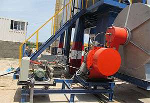
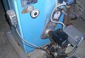
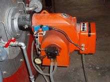
An oil burner is a heating device which burns #1, #2 and #6 heating oils, diesel fuel or other similar fuels. The fuel is atomized into a fine spray usually by forcing it under pressure through a nozzle which gives the resulting flame a specific flow rate, angle of spray and pattern (variations of a cone shape). This spray is usually ignited by an electric spark with the air being forced through around it at the end of a blast tube, by a fan driven by the oil burner motor.[2] The fuel pump is typically driven via a coupling connecting its shaft to that of the motor's. Oil burners also include combustion-proving devices to prevent out-of-control combustion - Primary Control; Safety Control; Cad Cell Control; Master Control; Fire-Eye Control are all common names for the 'combustion safety control'.
Fuel injection

Fuel is injected into the combustion chamber by a spray nozzle.
The nozzles are usually supplied with high pressure oil. Because of problems with erosion, and blockage due to lumps in the oil, they need frequent replacement, typically every year. Fuel nozzles are usually rated in fuel volume flow per unit time e.g. USGal/h (U.S. Gallons per hour).
A fuel nozzle is characterized by three features:
- Flow at 7 bar pump pressure (e.g. 0.65 USGal/h)
- Spray characteristic (e.g. "S")
- Spray angle (e.g. 60 °)
Alternatively fuel may be passed over a tiny orifice fed with compressed air. This arrangement is referred to as Babington atomiser/nozzle, named after its inventor Robert Babington.[3] As the oil flows over the nozzle, the fuel needn't be under any great pressure. If the pump can handle such the oil may even contain lumps such as scraps of food. Because it is only compressed air that passes through the orifice hole, such nozzles do not suffer much from erosion.
Oil pump

A fuel oil pump of two parts:
Gear pump assembly
This sucks the oil and increases the pressure in the nozzles to 15 bar maximum. Usually a gear pump of the sickle type is used. Gear pumps are used frequently in oil burners because of their simplicity, stability and low price.
Pressure regulator
To set the heat output of the burner, the rate of fuel delivery via the nozzle must be adjustable. This is often achieved by an adjustable pressure relief valve between the pump and the nozzle. When the set pressure is reached (usually 10 - 11 bar), this valve opens and allows excess oil to flow through a bypass back to the fuel tank or the pump suction side.
Electromagnetic valve
This allows fuel to be shut off from the sprayer by electrical control. It helps avoid drips when the valve is closed. It also eases the purging of the burner (and any boiler) of fuel mist during start up, or while restarting after a misfire. If the burner were not purged the oil/air mixture could explode dangerously.
Fan
The fan blows air into the combustion chamber. The rotor of the fan is powered by an electric motor.
Igniters
Some oil burners use glow bars which operate much like the glow plugs of a diesel engine
Many use high voltage generated by a voltage-step up transformer and use a spark plug to initiate ignition
Original oil burner transformers were copper wire conductors wrapped around an iron core. A standard type of transformer to this day. In the mid 90s electronic igniters replaced the copper and iron transformer,solving many problems related to the old style transformer. This new technology in igniters would soon replace all old style transformers throughout the oil burner industry. The new igniters would run cooler so the output voltage could be increased from 10,000 to 20,000 VAC. This increase of voltage would be more reliable, reduce delayed ignition, run cooler and all while using less energy. The voltage is high, but a standard igniter will only pull around 35 milliamp.
Photocell

A light dependent resistor (LDR) detects the flame. The LDR is an electrical resistor whose value changes by the amount of light that it is exposed to. The resistance decreases as the LDR is exposed to more light. The material is usually cadmium sulfide, hence the name "cad cell" for this component. In darkness the resistance is around 1 MΩ, while when exposed to light (from a flame) the resistance is significantly lower, around 75-300 Ω.
Capacitor start motor

The motor which drives the fan and the oil pump is usually a capacitor start motor. It is a vortex shortage tank motor because it also contains a short cage or cage holds. The difference with a three-phase motor is in the stator. Where the vortex power motor has three coils aligned at 120° in the stator, the capacitor start motor holds one main winding and one auxiliary winding aligned at 90°. The phase shift of 90° between the main winding and the auxiliary winding is achieved by a connected capacitor which feeds the auxiliary winding and is connected on the single-phase AC mains. The capacitor will achieve a phase shift of 90° between the main and the auxiliary winding, producing an acceptable initial torque. This motor is intended for continuous operation.
Order for starting an oil burner
- Connect the oil burner to a power source.
- Turn off the 'Emergency Shut Down' located on the furnace.
- Purge air from the burner/boiler.
- Atomize the fuel oil.
- Ignite the atomized fuel oil.
- Check with flame detection whether the fuel oil fired up.
If the burning does not catch on, the burner will go into alarm and must then be manually reset.
See also
- Boiler
- Central heating
- Coal burner
- Flame lift-off
- Gas burner
- Heater
- Heating oil
- Kerosene lamp
- LO-NOx burner
- Passive house
- Portable stove
- Rayburn Range
References
- ↑ "Diesel / Heavy Oil Dual Purpose Burner".
- ↑ James L. Kittle (1990). Home Heating & Air Conditioning Systems. McGraw-Hill Professional. ISBN 0-8306-3257-3.
- ↑ "Robert S. BABINGTON Nebulizer Fuel Burner". 1976.