Orifice plate
An orifice plate is a device used for measuring flow rate, for reducing pressure or for restricting flow (in the latter two cases it is often called a restriction plate). Either a volumetric or mass flow rate may be determined, depending on the calculation associated with the orifice plate. It uses the same principle as a Venturi nozzle, namely Bernoulli's principle which states that there is a relationship between the pressure of the fluid and the velocity of the fluid. When the velocity increases, the pressure decreases and vice versa.
Description
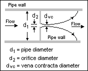
An orifice plate is a thin plate with a hole in it, which is usually placed in a pipe. When a fluid (whether liquid or gaseous) passes through the orifice, its pressure builds up slightly upstream of the orifice[1]:85–86 but as the fluid is forced to converge to pass through the hole, the velocity increases and the fluid pressure decreases. A little downstream of the orifice the flow reaches its point of maximum convergence, the vena contracta (see drawing to the right) where the velocity reaches its maximum and the pressure reaches its minimum. Beyond that, the flow expands, the velocity falls and the pressure increases. By measuring the difference in fluid pressure across tappings upstream and downstream of the plate, the flow rate can be obtained from Bernoulli's equation using coefficients established from extensive research.[2]:7.1–7.3
Application
Orifice plates are most commonly used to measure flow rates in pipes, when the fluid is single-phase (rather than being a mixture of gases and liquids, or of liquids and solids) and well-mixed, the flow is continuous rather than pulsating, the fluid occupies the entire pipe (precluding silt or trapped gas), the flow profile is even and well-developed and the fluid and flow rate meet certain other conditions. Under these circumstances and when the orifice plate is constructed and installed according to appropriate standards, the flow rate can easily be determined using published formulae based on substantial research and published in industry, national and international standards.[2]
Plates are commonly made with sharp-edged circular orifices and installed concentric with the pipe and with pressure tappings at one of three standard pairs of distances upstream and downstream of the plate; these types are covered by ISO 5167 and other major standards. There are many other possibilities. The edges may be rounded or conical, the plate may have an orifice the same size as the pipe except for a segment at top or bottom which is obstructed, the orifice may be installed eccentric to the pipe, and the pressure tappings may be at other positions. Variations on these possibilities are covered in various standards and handbooks. Each combination gives rise to different coefficients of discharge which can be predicted so long as various conditions are met, conditions which differ from one type to another.[2]
Once the orifice plate is designed and installed, the flow rate can often be indicated with an acceptably low uncertainty simply by taking the square root of the differential pressure across the orifice's pressure tappings and applying an appropriate constant. Even compressible flows of gases that vary in pressure and temperature may be measured with acceptable uncertainty by merely taking the square roots of the absolute pressure and/or temperature, depending on the purpose of the measurement and the costs of ancillary instrumentation.
Orifice plates are also used to reduce pressure or restrict flow, in which case they are often called restriction plates.[3][4]
Pressure tappings
There are three standard positions for pressure tappings (also called taps), commonly named as follows:
- Corner taps placed immediately upstream and downstream of the plate; convenient when the plate is provided with an orifice carrier incorporating tappings
- D and D/2 taps or radius taps placed one pipe diameter upstream and half a pipe diameter downstream of the plate; these can be installed by welding bosses to the pipe
- Flange taps placed 25.4 mm (1 inch) upstream and downstream of the plate, normally within specialised pipe flanges.
These types are covered by ISO 5167 and other major standards. Other types include
- 2½D and 8D taps or recovery taps placed 2.5 pipe diameters upstream and 8 diameters downstream, at which point the measured differential is equal to the unrecoverable pressure loss caused by the orifice
- Vena contracta tappings placed one pipe diameter upstream and at a position 0.3 to 0.9 diameters downstream, depending on the orifice type and size relative to the pipe, in the plane of minimum fluid pressure.
The measured differential pressure differs for each combination and so the coefficient of discharge used in flow calculations depends partly on the tapping positions.
The simplest installations use single tappings upstream and downstream, but in some circumstances these may be unreliable; they might be blocked by solids or gas-bubbles, or the flow profile might be uneven so that the pressures at the tappings are higher or lower than the average in those planes. In these situations multiple tappings can be used, arranged circumferentially around the pipe and joined by a piezometer ring, or (in the case of corner taps) annular slots running completely round the internal circumference of the orifice carrier.
Plate
Standards and handbooks are mainly concerned with sharp-edged thin plates. In these, the leading edge is sharp and free of burrs and the cylindrical section of the orifice is short, either because the entire plate is thin or because the downstream edge of the plate is bevelled. Exceptions include the quarter-circle or quadrant-edge orifice, which has a fully rounded leading edge and no cylindrical section, and the conical inlet or conical entrance plate which has a bevelled leading edge and a very short cylindrical section. The orifices are normally concentric with the pipe (the eccentric orifice is a specific exception) and circular (except in the specific case of the segmental or chord orifice, in which the plate obstructs just a segment of the pipe). Standards and handbooks stipulate that the upstream surface of the plate is particularly flat and smooth. Sometimes a small drain or vent hole is drilled through the plate where it meets the pipe, to allow condensate or gas bubbles to pass along the pipe.
Pipe
Standards and handbooks stipulate a well-developed flow profile; velocities will be lower at the pipe wall than in the centre but not eccentric or jetting. Similarly the flow downstream of the plate must be unobstructed, otherwise the downstream pressure will be affected. To achieve this, the pipe must be acceptably circular, smooth and straight for stipulated distances. Sometimes when it is impossible to provide enough straight pipe, flow conditioners such as tube bundles or plates with multiple holes are inserted into the pipe to straighten and develop the flow profile, but even these require a further length of straight pipe before the orifice itself. Some standards and handbooks also provide for flows from or into large spaces rather than pipes, stipulating that the region before or after the plate is free of obstruction and abnormalities in the flow.
Computation
Flow rates through an orifice plate can be calculated without specifically calibrating the individual flowmeter so long as the construction and installation of the device complies with the stipulations of the relevant standard or handbook. The calculation takes account of the fluid and fluid conditions, the pipe size, the orifice size and the measured differential pressure; it also takes account of the coefficient of discharge of the orifice plate, which depends upon the orifice type and the positions of the pressure tappings. With local pressure tappings (corner, flange and D+D/2), sharp-edged orifices have coefficients around 0.6 to 0.63,[5] while the coefficients for conical entrance plates are in the range 0.73 to 0.734 and for quarter-circle plates 0.77 to 0.85.[2] The coefficients of sharp-edged orifices vary more with fluids and flow rates than the coefficients of conical-entrance and quarter-circle plates, especially at low flows and high viscosities.
For compressible flows such as flows of gases or steam, an expansibility factor or expansion factor is also calculated. This factor is primarily a function of the ratio of the measured differential pressure to the fluid pressure and so can vary significantly as the flow rate varies, especially at high differential pressures and low static pressures.
The equations provided in American and European national and industry standards and the various coefficients used to differ from each other even to the extent of using different combinations of correction factors, but many are now closely aligned and give identical results; in particular, they use the same Reader-Harris/Gallagher (1998) equation for the coefficient of discharge for sharp-edged orifice plates. The equations below largely follow the notation of the international standard ISO 5167 and use SI units.[6][7]
Volume flow rate:

Mass flow rate:

Coefficient of discharge for sharp-edged orifice plates with corner, flange or D and D/2 tappings and no drain or vent hole (Reader-Harris/Gallagher equation):
- and if D < 71.2mm in which case this further term is added to C:
- [7][8]
- In the equation for C,
- and only the three following pairs of values for L1 and L'2 are valid:
- corner tappings:
- flange tappings: [8]
- D and D/2 tappings:


Expansibility factor, also called expansion factor, for sharp-edged orifice plates with corner, flange or D and D/2 tappings:

![\epsilon =1-(0.351+0.256\beta ^{4}+0.93\beta ^{8}){\bigg [}1-{\bigg (}{\frac {p_{2}}{p_{1}}}{\bigg )}^{{\frac {1}{\kappa }}}{\bigg ]}](../I/m/e8753687afd234568bc9c2e62e90e01fb887161c.svg)
- but for incompressible fluids, including most liquids

| where: | |
| = coefficient of discharge, dimensionless | |
| = internal orifice diameter under operating conditions, m | |
| = internal pipe diameter under operating conditions, m | |
| = fluid absolute static pressure in plane of upstream tapping, Pa | |
| = fluid absolute static pressure in plane of downstream tapping, Pa | |
| = mass flow rate, kg/s | |
| = volume flow rate, m3/s | |
| = pipe Reynolds number, , dimensionless | |
| = diameter ratio of orifice diameter to pipe diameter, , dimensionless | |
| = differential pressure, Pa | |
| = expansibility factor, also called expansion factor, dimensionless | |
| = isentropic exponent, often approximated by specific heat ratio, dimensionless | |
| = dynamic viscosity of the fluid, Pa.s | |
| = fluid density in plane of upstream tapping, kg/m³ |


Overall pressure loss
The overall pressure loss caused by an orifice plate is less than the differential pressure measured across tappings near the plate. For sharp-edged plates such as corner, flange or D and D/2 tappings, it can be approximated by the equation
- [7]:13

or
- [7]:13

| where | |
| = overall pressure loss, Pa | |
| and other symbols are as above |

Theory
Incompressible flow
By assuming steady-state, incompressible (constant fluid density), inviscid, laminar flow in a horizontal pipe (no change in elevation) with negligible frictional losses, Bernoulli's equation reduces to an equation relating the conservation of energy between two points on the same streamline:

or:

By continuity equation:
or and :


Solving for :


and:

The above expression for gives the theoretical volume flow rate. Introducing the beta factor as well as the discharge coefficient :


And finally introducing the meter coefficient which is defined as to obtain the final equation for the volumetric flow of the fluid through the orifice:


Multiplying by the density of the fluid to obtain the equation for the mass flow rate at any section in the pipe:[10][11][12][13]

| where: | |
| = volumetric flow rate (at any cross-section), m³/s | |
| = mass flow rate (at any cross-section), kg/s | |
| = coefficient of discharge, dimensionless | |
| = orifice flow coefficient, dimensionless | |
| = cross-sectional area of the pipe, m² | |
| = cross-sectional area of the orifice hole, m² | |
| = diameter of the pipe, m | |
| = diameter of the orifice hole, m | |
| = ratio of orifice hole diameter to pipe diameter, dimensionless | |
| = upstream fluid velocity, m/s | |
| = fluid velocity through the orifice hole, m/s | |
| = fluid upstream pressure, Pa with dimensions of kg/(m·s² ) | |
| = fluid downstream pressure, Pa with dimensions of kg/(m·s² ) | |
| = fluid density, kg/m³ |


Deriving the above equations used the cross-section of the orifice opening and is not as realistic as using the minimum cross-section at the vena contracta. In addition, frictional losses may not be negligible and viscosity and turbulence effects may be present. For that reason, the coefficient of discharge is introduced. Methods exist for determining the coefficient of discharge as a function of the Reynolds number.[11]
The parameter is often referred to as the velocity of approach factor[10] and multiplying the coefficient of discharge by that parameter (as was done above) produces the flow coefficient . Methods also exist for determining the flow coefficient as a function of the beta function and the location of the downstream pressure sensing tap. For rough approximations, the flow coefficient may be assumed to be between 0.60 and 0.75. For a first approximation, a flow coefficient of 0.62 can be used as this approximates to fully developed flow.

An orifice only works well when supplied with a fully developed flow profile. This is achieved by a long upstream length (20 to 40 pipe diameters, depending on Reynolds number) or the use of a flow conditioner. Orifice plates are small and inexpensive but do not recover the pressure drop as well as a venturi, nozzle, or venturi-nozzle does. Venturis also require much less straight pipe upstream. A venturi meter is more efficient, but usually more expensive and less accurate (unless calibrated in a laboratory) than an orifice plate.
Compressible flow
In general, equation (2) is applicable only for incompressible flows. It can be modified by introducing the expansibility factor, (also called the expansion factor) to account for the compressibility of gases.


is 1.0 for incompressible fluids and it can be calculated for compressible gases[11] using empirically determined formulae as shown above in Computation.
For smaller values of β (such as restriction plates with β less than 0.25 and discharge from tanks) rather than in flow measurement, if the fluid is compressible, the rate of flow depends on whether the flow has become choked. If it is, then the flow may be calculated as shown at choked flow, but the flow of real gases through thin-plate orifices never becomes fully choked[14] and the flow may be calculated as:
![{\dot {m}}=C\;A_{2}\;{\sqrt {2\;\rho _{1}\;P_{1}\;{\bigg (}{\frac {k}{k-1}}{\bigg )}{\bigg [}(P_{2}/P_{1})^{{2/k}}-(P_{2}/P_{1})^{{(k+1)/k}}{\bigg ]}}}](../I/m/331439fa7000dc9545673687abd9f4503b231027.svg)
| where: | |
| = specific heat ratio (), dimensionless | |
| = volume flow rate under upstream conditions, m³/s | |
| = real gas density under upstream conditions, kg/m³ | |
| and other symbols are as above |


See also
- Accidental release source terms
- Choked flow
- De Laval nozzle
- Flowmeter
- Pitot tube
- Restrictive flow orifice
- Rocket engine nozzle
- Venturi effect
- Advantages and disadvantages of orifice meter and venturi meter
References
- ↑ Linford, A (1961). Flow Measurement & Meters (2nd ed.). London: E. & F. N. Spon.
- 1 2 3 4 Miller, Richard W (1996). Flow Measurement Engineering Handbook. New York: McGraw-Hill. ISBN 0-07-042366-0.
- ↑ "Orifice Plates for Flow Measurement & Flow Restriction". Retrieved 1 February 2014.
- ↑ Flow of Fluids Through Valves, Fittings and Pipe. Ipswich: Crane. 1988. pp. 2–14.
- ↑ Bean, Howard S., ed. (April 1983). Fluid Meters (2nd printing with editorial changes of 6th ed.). The American Society of Mechanical Engineers (ASME).
- 1 2 ISO 5167-1:2003 Measurement of fluid flow by means of pressure differential devices inserted in circular cross-section conduits running full - Part 1: General principles and requirements. International Organization for Standardization (ISO). 1 March 2003.
- 1 2 3 4 5 6 ISO 5167-2:2003 Measurement of fluid flow by means of pressure differential devices inserted in circular cross-section conduits running full - Part 2: Orifice plates. International Organization for Standardization (ISO). 1 March 2003.
- 1 2 ISO 5167-2 uses the terms (2.8-D/25.4) and (25.4/D) - which both convert D into inches - because in that one clause of the standard, 5.3.2.1, D is in millimetres. This article presents D in metres throughout, so the terms are (2.8-D/0.0254) and (0.0254/D).
- ↑ ASME MFC-3M-2004 Sec. 2-4.3.2.2 stipulates a minimum of 0.8
- 1 2 Lecture, University of Sydney
- 1 2 3 Perry, Robert H. & Green, Don W. (1984). Perry's Chemical Engineers' Handbook (Sixth ed.). McGraw Hill. ISBN 0-07-049479-7.
- 1 2 Handbook of Chemical Hazard Analysis Procedures, Appendix B, Federal Emergency Management Agency, U.S. Dept. of Transportation, and U.S. Environmental Protection Agency, 1989. Handbook of Chemical Hazard Analysis, Appendix B Click on PDF icon, wait and then scroll down to page 391 of 520 PDF pages.
- 1 2 Risk Management Program Guidance For Offsite Consequence Analysis, U.S. EPA publication EPA-550-B-99-009, April 1999. Guidance for Offsite Consequence Analysis
- ↑ Cunningham (1951) first drew attention to the fact that choked flow will not occur across a standard, thin, square-edged orifice.[15] The mass flow rate through the orifice continues to increase as the downstream pressure is lowered to a perfect vacuum, though the mass flow rate increases slowly as the downstream pressure is reduced below the critical pressure.[16]
- ↑ Cunningham, R.G., "Orifice Meters with Supercritical Compressible Flow", Trans. ASME, Vol. 73, pp. 625-638, 1951
- ↑ Section 3 -- Choked Flow
- ↑ Methods For The Calculation Of Physical Effects Due To Releases Of Hazardous Substances (Liquids and Gases), PGS2 CPR 14E, Chapter 2, The Netherlands Organization Of Applied Scientific Research, The Hague, 2005. PGS2 CPR 14E