Precision rectifier
The precision rectifier, also known as a super diode, is a configuration obtained with an operational amplifier in order to have a circuit behave like an ideal diode and rectifier.[1] It is useful for high-precision signal processing.
The op-amp based precision rectifier should not be confused with the power MOSFET-based active rectification ideal diode.
Basic circuit
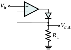
The basic circuit implementing such a feature is shown on the right, where  can be any load. When the input voltage is negative, there is a negative voltage on the diode, so it works like an open circuit, no current flows through the load, and the output voltage is zero.
When the input is positive, it is amplified by the operational amplifier which switches the diode on. Current flows through the load and, because of the feedback, the output voltage is equal to the input voltage.
The actual threshold of the super diode is very close to zero, but is not zero. It equals the actual threshold of the diode, divided by the gain of the operational amplifier.
This basic configuration has a problem so it is not commonly used. When the input becomes (even slightly) negative, the operational amplifier runs open loop, as there is no feedback signal through the diode. With a typical high open loop gain operational amplifier, the output saturates. If the input then becomes positive again, the op-amp has to get out of the saturated state before positive amplification can take place again. This change generates some ringing and takes some time, greatly reducing the frequency response of the circuit.
Improved circuit
.svg.png)
An alternative version is given on the right.
In this case, when the input is greater than zero, D1 is OFF and D2 is ON, so the output is zero because one side of  is connected to the virtual ground, and there is no current through it.
When the input is less than zero, D1 is ON and D2 is OFF, and the output is like the input with an amplification of
is connected to the virtual ground, and there is no current through it.
When the input is less than zero, D1 is ON and D2 is OFF, and the output is like the input with an amplification of  . Its input-output relationship is the following:
This circuit has the benefit that the op-amp never goes into saturation, but its output must change by two diode voltage drops (about 1.2 V) each time the input signal crosses zero. Hence, the slew rate of the operational amplifier, and its frequency response (gain-bandwidth product) will limit high frequency performance - especially for low signal levels - although an error of less than 1% at 100 kHz is possible.
Similar circuitry can be used to create a precision full-wave rectifier circuit.
Peak detector
With a little modification, the basic precision rectifier can be used for detecting signal level peaks. In the following circuit, a capacitor retains the peak voltage level of the signal, and a switch is used for resetting the detected level.

References
- ↑ Paul Horowitz and Winfield Hill, The Art of Electronics. 2nd ed. Cambridge University Press, Cambridge, 1989 ISBN 0-521-37095-7
External links
- Precision half-wave rectifier
- Precision full-wave rectifier
- Single op-amp full-wave rectifier circuits
- Rod Elliott's improved version
- Patent from 1982 (expired) detailing a simple very accurate design