Network topology
| Network science | ||||
|---|---|---|---|---|
| Network types | ||||
| Graphs | ||||
|
||||
| Models | ||||
|
||||
| ||||
|
||||
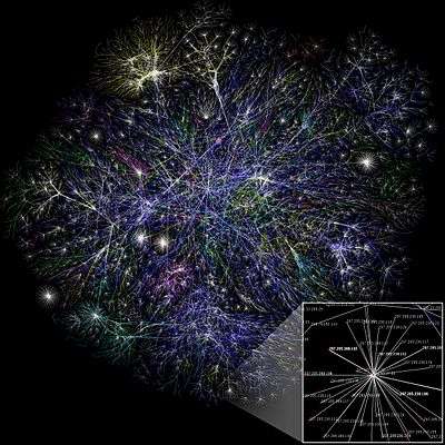
Network topology is the arrangement of the various elements (links, nodes, etc.) of a computer network.[1][2] Essentially, it is the topological[3] structure of a network and may be depicted physically or logically. Physical topology is the placement of the various components of a network, including device location and cable installation, while logical topology illustrates how data flows within a network, regardless of its physical design. Distances between nodes, physical interconnections, transmission rates, or signal types may differ between two networks, yet their topologies may be identical.
An example is a local area network (LAN). Any given node in the LAN has one or more physical links to other devices in the network; graphically mapping these links results in a geometric shape that can be used to describe the physical topology of the network. Conversely, mapping the data flow between the components determines the logical topology of the network.
Topology
Two basic categories of network topologies exist, physical topologies and logical topologies.[4]
The cabling layout used to link devices is the physical topology of the network. This refers to the layout of cabling, the locations of nodes, and the interconnections between the nodes and the cabling.[1] The physical topology of a network is determined by the capabilities of the network access devices and media, the level of control or fault tolerance desired, and the cost associated with cabling or telecommunications circuits.
In contrast, logical topology is the way that the signals act on the network media, or the way that the data passes through the network from one device to the next without regard to the physical interconnection of the devices. A network's logical topology is not necessarily the same as its physical topology. For example, the original twisted pair Ethernet using repeater hubs was a logical bus topology carried on a physical star topology. Token ring is a logical ring topology, but is wired as a physical star from the media access unit. Logical topologies are often closely associated with media access control methods and protocols. Some networks are able to dynamically change their logical topology through configuration changes to their routers and switches.
Classification
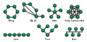
The study of network topology recognizes eight basic topologies: point-to-point, bus, star, ring or circular, mesh, tree, hybrid, or daisy chain.[5]
Point-to-point
The simplest topology with a dedicated link between two endpoints. Easiest to understand, of the variations of point-to-point topology, is a point-to-point communications channel that appears, to the user, to be permanently associated with the two endpoints. A child's tin can telephone is one example of a physical dedicated channel.
Using circuit-switching or packet-switching technologies, a point-to-point circuit can be set up dynamically and dropped when no longer needed. Switched point-to-point topologies are the basic model of conventional telephony.
The value of a permanent point-to-point network is unimpeded communications between the two endpoints. The value of an on-demand point-to-point connection is proportional to the number of potential pairs of subscribers and has been expressed as Metcalfe's Law.
Bus
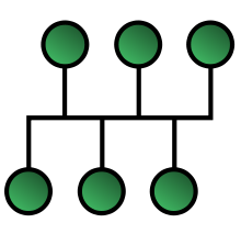
In local area networks where bus topology is used, each node is connected to a single cable, by the help of interface connectors. This central cable is the backbone of the network and is known as the bus (thus the name). A signal from the source travels in both directions to all machines connected on the bus cable until it finds the intended recipient. If the machine address does not match the intended address for the data, the machine ignores the data. Alternatively, if the data matches the machine address, the data is accepted. Because the bus topology consists of only one wire, it is rather inexpensive to implement when compared to other topologies. However, the low cost of implementing the technology is offset by the high cost of managing the network. Additionally, because only one cable is utilized, it can be the single point of failure.
Linear bus
The type of network topology in which all of the nodes of the network are connected to a common transmission medium which has exactly two endpoints (this is the 'bus', which is also commonly referred to as the backbone, or trunk) – all data that is transmitted between nodes in the network is transmitted over this common transmission medium and is able to be received by all nodes in the network simultaneously.[1]
Note: When the electrical signal reaches the end of the bus, the signal is reflected back down the line, causing unwanted interference. As a solution, the two endpoints of the bus are normally terminated with a device called a terminator that prevents this reflection.
Distributed bus
The type of network topology in which all of the nodes of the network are connected to a common transmission medium which has more than two endpoints that are created by adding branches to the main section of the transmission medium – the physical distributed bus topology functions in exactly the same fashion as the physical linear bus topology (i.e., all nodes share a common transmission medium).
Star

In local area networks with a star topology, each network host is connected to a central hub with a point-to-point connection. So it can be said that every computer is indirectly connected to every other node with the help of the hub. In Star topology, every node (computer workstation or any other peripheral) is connected to a central node called hub, router or switch. The switch is the server and the peripherals are the clients. The network does not necessarily have to resemble a star to be classified as a star network, but all of the nodes on the network must be connected to one central device. All traffic that traverses the network passes through the central hub. The hub acts as a signal repeater. The star topology is considered the easiest topology to design and implement. An advantage of the star topology is the simplicity of adding additional nodes. The primary disadvantage of the star topology is that the hub represents a single point of failure.
Extended star
A type of network topology in which a network that is based upon the physical star topology has one or more repeaters between the central node and the peripheral or 'spoke' nodes, the repeaters being used to extend the maximum transmission distance of the point-to-point links between the central node and the peripheral nodes beyond that which is supported by the transmitter power of the central node or beyond that which is supported by the standard upon which the physical layer of the physical star network is based.
If the repeaters in a network that is based upon the physical extended star topology are replaced with hubs or switches, then a hybrid network topology is created that is referred to as a physical hierarchical star topology, although some texts make no distinction between the two topologies.
Distributed Star
A type of network topology that is composed of individual networks that are based upon the physical star topology connected in a linear fashion – i.e., 'daisy-chained' – with no central or top level connection point (e.g., two or more 'stacked' hubs, along with their associated star connected nodes or 'spokes').
Ring
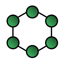
A ring topology is a bus topology in a closed loop. Data travels around the ring in one direction. When one node sends data to another, the data passes through each intermediate node on the ring until it reaches its destination. The intermediate nodes repeat (retransmit) the data to keep the signal strong.[4] Every node is a peer; there is no hierarchical relationship of clients and servers. If one node is unable to retransmit data, it severs communication between the nodes before and after it in the bus.
Mesh
The value of fully meshed networks is proportional to the exponent of the number of subscribers, assuming that communicating groups of any two endpoints, up to and including all the endpoints, is approximated by Reed's Law.
Fully connected network
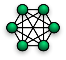
In a fully connected network, all nodes are interconnected. (In graph theory this is called a complete graph.) The simplest fully connected network is a two-node network. A fully connected network doesn't need to use packet switching or broadcasting. However, since the number of connections grows quadratically with the number of nodes:

This makes it impractical for large networks.
Partially connected network
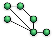
In a partially connected network, certain nodes are connected to exactly one other node; but some nodes are connected to two or more other nodes with a point-to-point link. This makes it possible to make use of some of the redundancy of mesh topology that is physically fully connected, without the expense and complexity required for a connection between every node in the network.
Hybrid
Hybrid networks combine two or more topologies in such a way that the resulting network does not exhibit one of the standard topologies (e.g., bus, star, ring, etc.). For example, a tree network (or star-bus network) is a hybrid topology in which star networks are interconnected via bus networks.[6][7] However, a tree network connected to another tree network is still topologically a tree network, not a distinct network type. A hybrid topology is always produced when two different basic network topologies are connected.
A star-ring network consists of two or more ring networks connected using a multistation access unit (MAU) as a centralized hub.
Snowflake topology is a star network of star networks.
Two other hybrid network types are hybrid mesh and hierarchical star.[6]
Daisy chain
Except for star-based networks, the easiest way to add more computers into a network is by daisy-chaining, or connecting each computer in series to the next. If a message is intended for a computer partway down the line, each system bounces it along in sequence until it reaches the destination. A daisy-chained network can take two basic forms: linear and ring.
- A linear topology puts a two-way link between one computer and the next. However, this was expensive in the early days of computing, since each computer (except for the ones at each end) required two receivers and two transmitters.
- By connecting the computers at each end, a ring topology can be formed. An advantage of the ring is that the number of transmitters and receivers can be cut in half, since a message will eventually loop all of the way around. When a node sends a message, the message is processed by each computer in the ring. If the ring breaks at a particular link then the transmission can be sent via the reverse path thereby ensuring that all nodes are always connected in the case of a single failure.
Centralization
The star topology reduces the probability of a network failure by connecting all of the peripheral nodes (computers, etc.) to a central node. When the physical star topology is applied to a logical bus network such as Ethernet, this central node (traditionally a hub) rebroadcasts all transmissions received from any peripheral node to all peripheral nodes on the network, sometimes including the originating node. All peripheral nodes may thus communicate with all others by transmitting to, and receiving from, the central node only. The failure of a transmission line linking any peripheral node to the central node will result in the isolation of that peripheral node from all others, but the remaining peripheral nodes will be unaffected. However, the disadvantage is that the failure of the central node will cause the failure of all of the peripheral nodes.
If the central node is passive, the originating node must be able to tolerate the reception of an echo of its own transmission, delayed by the two-way round trip transmission time (i.e. to and from the central node) plus any delay generated in the central node. An active star network has an active central node that usually has the means to prevent echo-related problems.
A tree topology (a.k.a. hierarchical topology) can be viewed as a collection of star networks arranged in a hierarchy. This tree has individual peripheral nodes (e.g. leaves) which are required to transmit to and receive from one other node only and are not required to act as repeaters or regenerators. Unlike the star network, the functionality of the central node may be distributed.
As in the conventional star network, individual nodes may thus still be isolated from the network by a single-point failure of a transmission path to the node. If a link connecting a leaf fails, that leaf is isolated; if a connection to a non-leaf node fails, an entire section of the network becomes isolated from the rest.
To alleviate the amount of network traffic that comes from broadcasting all signals to all nodes, more advanced central nodes were developed that are able to keep track of the identities of the nodes that are connected to the network. These network switches will "learn" the layout of the network by "listening" on each port during normal data transmission, examining the data packets and recording the address/identifier of each connected node and which port it is connected to in a lookup table held in memory. This lookup table then allows future transmissions to be forwarded to the intended destination only.
Decentralization
In a partially connected mesh topology, there are at least two nodes with two or more paths between them to provide redundant paths in case the link providing one of the paths fails. Decentralization is often used to compensate for the single-point-failure disadvantage that is present when using a single device as a central node (e.g., in star and tree networks). A special kind of mesh, limiting the number of hops between two nodes, is a hypercube. The number of arbitrary forks in mesh networks makes them more difficult to design and implement, but their decentralized nature makes them very useful. In 2012 the IEEE published the Shortest Path Bridging protocol to ease configuration tasks and allows all paths to be active which increases bandwidth and redundancy between all devices.[8][9][10][11][12]
This is similar in some ways to a grid network, where a linear or ring topology is used to connect systems in multiple directions. A multidimensional ring has a toroidal topology, for instance.
A fully connected network, complete topology, or full mesh topology is a network topology in which there is a direct link between all pairs of nodes. In a fully connected network with n nodes, there are n(n-1)/2 direct links. Networks designed with this topology are usually very expensive to set up, but provide a high degree of reliability due to the multiple paths for data that are provided by the large number of redundant links between nodes. This topology is mostly seen in military applications.
See also
References
- 1 2 3 Groth, David; Toby Skandier (2005). Network+ Study Guide, Fourth Edition. Sybex, Inc. ISBN 0-7821-4406-3.
- ↑ ATIS committee PRQC. "mesh topology". ATIS Telecom Glossary 2007. Alliance for Telecommunications Industry Solutions. Retrieved 2008-10-10.
- ↑ Chiang, Mung; Yang, Michael (2004). "Towards Network X-ities From a Topological Point of View: Evolvability and Scalability" (PDF). Proc. 42nd Allerton Conference.
- 1 2 Inc, S., (2002) . Networking Complete. Third Edition. San Francisco: Sybex
- ↑ Bicsi, B. (2002). Network Design Basics for Cabling Professionals. McGraw-Hill Professional. ISBN 9780071782968.
- 1 2 Sosinsky, Barrie A. (2009). "Network Basics". Networking Bible. Indianapolis: Wiley Publishing. p. 16. ISBN 978-0-470-43131-3. OCLC 359673774. Retrieved 2016-03-26.
- ↑ Bradley, Ray. Understanding Computer Science (for Advanced Level): The Study Guide. Cheltenham: Nelson Thornes. p. 244. ISBN 978-0-7487-6147-0. OCLC 47869750. Retrieved 2016-03-26.
- ↑ "Avaya Extends the Automated Campus to End the Network Waiting Game". Avaya. 1 April 2014. Retrieved 18 April 2014.
- ↑ Peter Ashwood-Smith (24 February 2011). "Shortest Path Bridging IEEE 802.1aq Overview" (PDF). Huawei. Retrieved 11 May 2012.
- ↑ Jim Duffy (11 May 2012). "Largest Illinois healthcare system uproots Cisco to build $40M private cloud". PC Advisor. Retrieved 11 May 2012.
Shortest Path Bridging will replace Spanning Tree in the Ethernet fabric.
- ↑ "IEEE Approves New IEEE 802.1aq Shortest Path Bridging Standard". Tech Power Up. 7 May 2012. Retrieved 11 May 2012.
- ↑ D. Fedyk, Ed.,; P. Ashwood-Smith, Ed.,; D. Allan, A. Bragg,; P. Unbehagen (April 2012). "IS-IS Extensions Supporting IEEE 802.1aq". IETF. Retrieved 12 May 2012.
External links
| Wikimedia Commons has media related to Topology (Network). |
- Tetrahedron Core Network: Application of a tetrahedral structure to create a resilient partial-mesh 3-dimensional campus backbone data network