Press brake
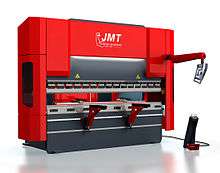

A press brake is a machine tool for bending sheet and plate material, most commonly sheet metal.[1] It forms predetermined bends by clamping the work piece between a matching punch and die.[2]
Typically, two C-frames form the sides of the press brake, connected to a table at the bottom and on a movable beam at the top. The bottom tool is mounted on the table with the top tool mounted on the upper beam.[3]
Types
A brake can be described by basic parameters, such as the force or tonnage and the working length.[1] Additional parameters include the stroke length, the distance between the frame uprights or side housings, distance to the back gauge, and work height. The upper beam usually operates at a speed ranging from 1 to 15 mm/s.[3]
There are several types of brakes as described by the means of applying force: mechanical, pneumatic, hydraulic, and servo-electric.
In a mechanical press, energy is added to a flywheel with an electric motor. A clutch engages the flywheel to power a crank mechanism that moves the ram vertically. Accuracy and speed are two advantages of the mechanical press.[4]
Hydraulic presses operate by means of two synchronized hydraulic cylinders on the C-frames moving the upper beam.[3][4] Servo-electric brakes use a servo-motor to drive a ballscrew or belt drive to exert tonnage on the ram.
Pneumatic presses utilize air pressure to develop tonnage on the ram.
Until the 1950s, mechanical brakes dominated the world market. The advent of better hydraulics and computer controls have led to hydraulic machines being the most popular.
Pneumatic and servo-electric machines are typically used in lower tonnage applications. Hydraulic brakes produce accurate high quality products, are reliable, use little energy and are safer because, unlike flywheel-driven presses, the motion of the ram can be easily stopped at any time in response to a safety device, e.g. a light curtain.

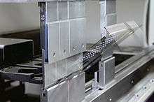
Recent improvements are mainly in the control and a device called a backgauge. A back gauge is a device that can be used to accurately position a piece of metal so that the brake puts the bend in the correct place. Furthermore, the back gauge can be programmed to move between bends to repeatedly make complex parts. Early brakes relied on the tooling to determine the bend angle of the bend. The animation to the right shows the operation of the back gauge, setting the distance from the edge of the material or previous bend to the center of the die.
Press brakes often include multi-axis computer-controlled back gauges. Optical sensors allow operators to make adjustments during the bending process. These sensors send real-time data about the bending angle in the bend cycle to machine controls that adjust process parameters.[3]
Dies
Press brakes can be used for many different forming jobs with the right die design. Types of dies include:[4]
- V-dies—the most common type of die. The bottom dies can be made with different-sized die openings to handle a variety of materials and bend angles.
- Rotary bending dies—a cylindrical shape with an 88-degree V-notch cut along its axis is seated in the "saddle" of the punch. The die is an anvil over which the rocker bends the sheet.
- 90 degree dies—largely used for bottoming operations. The die opening dimension depends on material thickness.
- Acute angle (air-bending) dies—used in air bending, these can actually be used to produce acute, 90 degree, and obtuse angles by varying how deeply the punch enters the die by adjusting the ram.
- Gooseneck (return-flanging) dies—The punch is designed to allow for clearance of already formed flanges
- Offset dies—a combination punch and die set that bends two angles in one stroke to produce a Z shape.
- Hemming dies—two-stage dies combining an acute angle die with a flattening tool.
- Seaming dies—There are a number of ways to build dies to produce seams in sheets and tubes.
- Radius dies—A radiussed bend can be produced by a rounded punch. The bottom die may be a V-die or may include a spring pad or rubber pad to form the bottom of the die.
- Beading dies—A bead or a "stopped rib" may be a feature that stiffens the resulting part. The punch has a rounded head with flat shoulders on each side of the bead. The bottom die is the inverse of the punch.
- Curling dies—The die forms a curled or coiled edge on the sheet.
- Tube- and pipe-forming dies—a first operation bends the edges of the sheet to make the piece roll up. Then a die similar to a curling die causes the tube to be formed. Larger tubes are formed over a mandrel.
- Four-way die blocks—A single die block may have a V machined into each of four sides for ease of changeover of small jobs.
- Channel-forming dies—A punch can be pressed into a die to form two angles at the bottom of the sheet, forming an angular channel.
- U-bend dies—Similar to channel forming, but with a rounded bottom. Spring back may be a problem and a means may need to be provided for countering it.
- Box-forming dies—While a box may be formed by simple angle bends on each side, the different side lengths of a rectangular box must be accommodated by building the punch in sections. The punch also needs to be high enough to accommodate the height of the resulting box's sides.
- Corrugating dies—Such dies have a wavy surface and may involve spring-loaded punch elements.
- Multiple-bend dies—A die set may be built in the shape of the desired profile and form several bends on a single stroke of the press.
- Rocker-type dies—A rocker insert in the punch may allow for some side-to-side motion, in addition to the up-and-down motion of the press.
See also
- Brake (sheet metal bending)
- Bending Machine (flat metal bending)
- Bending
- Bending (mechanics)
- Tube bending
- Spring Back Compensation
References
- 1 2 Fournier, Ron; Fournier, Sue (1989), Sheet metal handbook, HPBooks, p. 37, ISBN 978-0-89586-757-5
- ↑ Parker, Dana T. Building Victory: Aircraft Manufacturing in the Los Angeles Area in World War II, p. 29, 83, Cypress, CA, 2013. ISBN 978-0-9897906- 0-4.
- 1 2 3 4 "Press Brake Bending: Methods and Challenges". Metalforming. Precision Metalforming Association. August 2008.
- 1 2 3 Tool and Manufacturing Engineers Handbook (TMEH), Volume 2, Forming. Society of Manufacturing Engineers, 1984.
Further reading
- Benson, Steve D. Press Brake Technology: A Guide to Precision Sheet Metal Bending. Society of Manufacturing Engineers, 1997. ISBN 978-0-87263-483-1