Push–pull output
.png)
A push–pull amplifier is a type of electronic circuit that uses a pair of active devices that alternately supply current to, or absorb current from, a connected load. Push–pull outputs are present in TTL and CMOS digital logic circuits and in some types of amplifiers, and are usually realized as a complementary pair of transistors, one dissipating or sinking current from the load to ground or a negative power supply, and the other supplying or sourcing current to the load from a positive power supply.
A push–pull amplifier is more efficient than a single-ended "class-A" amplifier. The output power that can be achieved is higher than the continuous dissipation rating of either transistor or tube used alone and increases the power available for a given supply voltage. Symmetrical construction of the two sides of the amplifier means that even-order harmonics are cancelled, which can reduce distortion.[1] DC current is cancelled in the output, allowing a smaller output transformer to be used than in a single-ended amplifier. However, the push–pull amplifier requires a phase-splitting component that adds complexity and cost to the system; use of center-tapped transformers for input and output is a common technique but adds weight and restricts performance. If the two parts of the amplifier do not have identical characteristics, distortion can be introduced as the two halves of the input waveform are amplified unequally. Crossover distortion can be created near the zero point of each cycle as one device is cut off and the other device enters its active region.
Push-pull circuits are widely used in many amplifier output stages. A pair of audion tubes connected in push–pull is described in Edwin H. Colpitts' US patent 1137384 granted in 1915, although the patent does not specifically claim the push–pull connection.[2] The technique was well-known at that time [3] and the principle had been claimed in an 1895 patent predating electronic amplifiers.[4] Possibly the first commercial product using a push–pull amplifier was the RCA Balanced amplifier released in 1924 for use with their Radiola III regenerative broadcast receiver.[5] By using a pair of low-power vacuum tubes in push–pull configuration, the amplifier allowed the use of a loudspeaker instead of headphones, while providing acceptable battery life with low standby power consumption.[6] The technique continues to be used in audio, radio frequency, digital and power electronics systems today.
Digital circuits

A digital use of a push–pull configuration is the output of TTL and related families. The upper transistor is functioning as an active pull-up, in linear mode, while the lower transistor works digitally. For this reason they aren't capable of supplying as much current as they can sink (typically 20 times less). Because of the way these circuits are drawn schematically, with two transistors stacked vertically, normally with a level shifting diode in between, they are called "totem pole" outputs.
A disadvantage of simple push–pull outputs is that two or more of them cannot be connected together, because if one tried to pull while another tried to push, the transistors could be damaged. To avoid this restriction, some push–pull outputs have a third state in which both transistors are switched off. In this state, the output is said to be floating (or, to use a proprietary term, tri-stated).
The alternative to a push–pull output is a single switch that connects the load either to ground (called an open collector or open drain output) or to the power supply (called an open-emitter or open-source output).
Analog circuits
A conventional amplifier stage which is not push–pull is sometimes called single-ended to distinguish it from a push–pull circuit.
In analog push–pull power amplifiers the two output devices operate in antiphase (i.e. 180° apart). The two antiphase outputs are connected to the load in a way that causes the signal outputs to be added, but distortion components due to non-linearity in the output devices to be subtracted from each other; if the non-linearity of both output devices is similar, distortion is much reduced. Symmetrical push–pull circuits must cancel even order harmonics, like f2, f4, f6 and therefore promote odd order harmonics, like (f1), f3, f5 when driven into the nonlinear range.
A push–pull amplifier produces less distortion than a single-ended one. This allows a class-A or AB push–pull amplifier to have less distortion for the same power as the same devices used in single-ended configuration. Class AB and class B dissipate less power for the same output than class A; distortion can be kept low by negative feedback and by biassing the output stage to reduce crossover distortion.
A class - B push–pull amplifier is more efficient than a class-A power amplifier because each output device amplifies only half the output waveform and is cut off during the opposite half. It can be shown that the theoretical full power efficiency (AC power in load compared to DC power consumed) of a push–pull stage is approximately 78.5%. This compares with a class-A amplifier which has efficiency of 25% if directly driving the load and no more than 50% for a transformer coupled output.[7] A push–pull amplifier draws little power with zero signal, compared to a class-A amplifier that draws constant power. Power dissipation in the output devices is roughly one-fifth of the output power rating of the amplifier.[7] A class-A amplifier, by contrast, must use a device capable of dissipating several times the output power.
The output of the amplifier may be direct-coupled to the load, coupled by a transformer, or connected through a dc blocking capacitor. Where both positive and negative power supplies are used, the load can be returned to the midpoint (ground) of the power supplies. A transformer allows a single polarity power supply to be used, but limits the low-frequency response of the amplifier. Similarly, with a single power supply, a capacitor can be used to block the DC level at the output of the amplifier.[8]
Where bipolar junction transistors are used, the bias network must compensate for the negative temperature coefficient of the transistors' base to emitter voltage. This can be done by including a small value resistor between emitter and output. Also, the driving circuit can have silicon diodes mounted in thermal contact with the output transistors to provide compensation.
Push–pull transistor output stages
Categories include:
Transformer-output transistor power amplifiers
It is now very rare to use output transformers with transistor amplifiers, although such amplifiers offer the best opportunity for matching the output devices (with only PNP or only NPN devices required).
Totem-pole push–pull output stages
Two matched transistors of the same polarity can be arranged to supply opposite halves of each cycle without the need for an output transformer, although in doing so the driver circuit often is asymmetric and one transistor will be used in a Common-emitter configuration while the other is used as an Emitter follower. This arrangement is less used today than during the 1970s; it can be implemented with few transistors (not so important today) but is relatively difficult to balance and so keep to a low distortion.
Symmetrical push–pull
Each half of the output pair "mirror" the other, in that an NPN (or N-Channel FET) device in one half will be matched by a PNP (or P-Channel FET) in the other. This type of arrangement tends to give lower distortion than quasi-symmetric stages because even harmonics are cancelled more effectively with greater symmetry.
Quasi-symmetrical push–pull
In the past when good quality PNP complements for high power NPN silicon transistors were limited, a workaround was to use identical NPN output devices, but fed from complementary PNP and NPN driver circuits in such a way that the combination was close to being symmetrical (but never as good as having symmetry throughout). Distortion due to mismatched gain on each half of the cycle could be a significant problem.
Super-symmetric output stages
Employing some duplication in the whole driver circuit, to allow symmetrical drive circuits can improve matching further, although driver asymmetry is a small fraction of the distortion generating process. Using a bridge-tied load arrangement allows a much greater degree of matching between positive and negative halves, compensating for the inevitable small differences between NPN and PNP devices.
Square-law push–pull
The output devices, usually MOSFETs or vacuum tubes, are configured so that their square-law transfer characteristics (that generate second-harmonic distortion if used in a single-ended circuit) cancel distortion to a large extent. That is, as one transistor's gate-source voltage increases, the drive to the other device is reduced by the same amount and the drain (or plate) current change in the second device approximately corrects for the non-linearity in the increase of the first.[9]
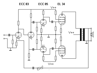
Push–pull tube (valve) output stages
Vacuum tubes (valves) are not available in complementary types (as are pnp/npn transistors), so the tube push–pull amplifier has a pair of identical output tubes or groups of tubes with the control grids driven in antiphase. These tubes drive current through the two halves of the primary winding of a center-tapped output transformer. Signal currents add, while the distortion signals due to the non-linear characteristic curves of the tubes subtract. These amplifiers were first designed long before the development of solid-state electronic devices; they are still in use by both audiophiles and musicians who consider them to sound better.
Vacuum tube push-pull amplifiers usually use an output transformer, although Output-transformerless (OTL) tube stages exist (such as the SEPP/SRPP and the White Cathode Follower below). The phase-splitter stage is usually another vacuum tube but a transformer with a center-tapped secondary winding was occasionally used in some designs. Because these are essentially square-law devices, the comments regarding distortion cancellation mentioned above apply to most push-pull tube designs when operated in class A (i.e. neither device is driven to its non-conducting state).
A Single Ended Push-Pull (SEPP, SRPP or mu-follower[10]) output stage, orginally called the Series-Balanced amplifier (US patent 2,310,342, Feb 1943). is similar to a totem-pole arrangement for transistors in that two devices are in series between the power supply rails, but the input drive goes only to one of the devices, the bottom one of the pair; hence the (seemingly contradictory) Single-Ended description. The output is taken from the cathode of the top (not directly driven) device, which acts part way between a constant current source and a cathode follower but receiving some drive from the plate (anode) circuit of the bottom device. The drive to each tube therefore might not be equal, but the circuit tends to keep the current through the bottom device somewhat constant throughout the signal, increasing the power gain and reducing distortion compared with a true single-tube single-ended output stage.
The White Cathode Follower (Patent 2,358,428, Sep 1944 by E. L. C. White) is similar to the SEPP design above, but the signal input is to the top tube, acting as a cathode follower, but one where the bottom tube (in common cathode configuration) if fed (usually via a step-up transformer) from the current in the plate (anode) of the top device. It essentially reverses the roles of the two devices in SEPP. The bottom tube acts part way between a constant current sink and an equal partner in the push-pull workload. Again, the drive to each tube therefore might not be equal.
Transistor versions of the SEPP and White follower do exist, but are rare.
Ultra-linear push–pull
A so-called ultra-linear push–pull amplifier uses either pentodes or tetrodes with their screen grid fed from a percentage of the primary voltage on the output transformer. This gives efficiency and distortion that is a good compromise between triode (or triode-strapped) power amplifier circuits and conventional pentode or tetrode output circuits where the screen is fed from a relatively constant voltage source.
See also
- Single-ended triode
- Push–pull converter for more details on implementation
- Open collector
References
- ↑ Joe Carr, RF Components and Circuits, Newnes, page 84
- ↑ Donald Monroe McNicol, Radios' Conquest of Space: The Experimental Rise in Radio Communication Taylor & Francis, 1946 page 348
- ↑ http://www.leagle.com/xmlResult.aspx?page=5&xmldoc=193278360F2d723_1537.xml&docbase=CSLWAR1-1950-1985&SizeDisp=7 WESTERN ELECTRIC CO. v. WALLERSTEIN retrieved 12/12/12
- ↑ US Patent 549,477 Local Transmitter Circuit for Telephones., W. W. Dean
- ↑ Radios - RCA Radiola Balanced Amplifier 1924
- ↑ Gregory Malanowski The Race for Wireless: How Radio Was Invented (or Discovered?), AuthorHouse, 2011 ISBN 1463437501 pages 66-67, page 144
- 1 2 Maurice Yunik Design of Modern Transistor Circuits, Prentice-Hall 1973 ISBN 0-13-201285-5 pp. 340-353
- ↑ Donald G. Fink, ed. Electronics Engineer's Handbook, McGraw Hill 1975 ISBN 978-0-07-020980-0 pp. 13-23 through 13-24
- ↑ Ian Hegglun. "Practical Square-law Class-A Amplifier Design". Linear Audio - Volume 1.
- ↑ "SRPP Decoded". The Tube CAD Journal. Retrieved 7 November 2016.