Railway brake
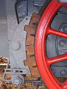

Brakes are used on the cars of railway trains to enable deceleration, control acceleration (downhill) or to keep them standing when parked. While the basic principle is familiar from road vehicle usage, operational features are more complex because of the need to control multiple linked carriages and to be effective on vehicles left without a prime mover. Clasp brakes are one type of brakes historically used on trains.
Early days
In the earliest days of railways, braking technology was primitive. The first trains had brakes operative on the locomotive tender and on vehicles in the train, where "porters" or, in the United States brakemen, travelling for the purpose on those vehicles operated the brakes. Some railways fitted a special deep-noted brake whistle to locomotives to indicate to the porters the necessity to apply the brakes. All the brakes at this stage of development were applied by operation of a screw and linkage to brake blocks applied to wheel treads, and these brakes could be used when vehicles were parked. In the earliest times, the porters travelled in crude shelters outside the vehicles, but "assistant guards" who travelled inside passenger vehicles, and who had access to a brake wheel at their posts supplanted them.
The braking effort achievable was limited, and an early development was the application of a steam brake to locomotives, where boiler pressure could be applied to brake blocks on the locomotive wheels. It was also unreliable, as the application of brakes by guards depended upon them hearing and responding quickly to a whistle for brakes.
As train speeds increased, it became essential to provide some more powerful braking system capable of instant application and release by the train driver, described as a continuous brake because it would be effective continuously along the length of the train.
In the UK, the Abbots Ripton rail accident in January 1876 was aggravated by the long stopping distances of express trains without continuous brakes, which -it became clear- in adverse conditions could considerably exceed those assumed when positioning signals. This had become apparent from the trials on railway brakes carried out at Newark in the previous year, to assist a Royal Commission then considering railway accidents. In the words of a contemporary railway official, these
showed that under normal conditions it required a distance of 800 to 1200 yards to bring a train to rest when travelling at 45½ to 48½ mph, this being much below the ordinary travelling speed of the fastest express trains. Railway officials were not prepared for this result and the necessity for a great deal more brake power was at once admitted[1]
More precise results from the Newark trials are not to hand; trials conducted after Abbots Ripton reported the following (for an express train roughly matching one of those involved, like it on a 1 in 200 fall, but unlike it braking under favorable conditions)[2]
| Braking system | Train speed | Distance | Stopping time (s) | ||
|---|---|---|---|---|---|
| mph | km/h | yd | m | ||
| Continuous (vacuum) | 45 | 72 | 410 | 370 | 26 |
| Continuous (vacuum) | 45 | 72 | 451 | 412 | 30 |
| 3 brake vans | 40.9 | 65.8 | 800 | 730 | 59 |
| 2 brake vans | 40.9 | 65.8 | 631 | 577 | 44 |
| 2 brake vans | 45 | 72 | 795 | 727 | 55 |
| 1 brake van | 45 | 72 | 1,125 | 1,029 | 70 |
However, there was no clear technical solution to the problem, because of the necessity of achieving a reasonably uniform rate of braking effort throughout a train, and because of the necessity to add and remove vehicles from the train at frequent points on the journey. (At these dates, unit trains were a rarity).
The chief types of solution were:
- The chain brake, such as the Heberlein brake, in which a chain was connected continuously along the train. When pulled tight it activated a friction clutch that used the rotation of the wheels to tighten a brake system at that point; this system has severe limitations in length of train capable of being handled, and of achieving good adjustment.
- Hydraulic brakes. As with (passenger) car brakes; actuating pressure to apply brakes was transmitted hydraulically. These found some favor in the UK (e.g. with the Midland and Great Eastern Railways), but even in the UK problems were found with the water used as brake fluid freezing [3]
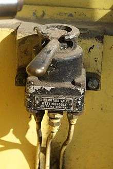
- The Westinghouse air brake system. In this system, air reservoirs are provided on every vehicle and the locomotive charges the train pipe with a positive air pressure, which releases the vehicle brakes and charges the air reservoirs on the vehicles. If the driver applies the brakes, his brake valve releases air from the train pipe, and triple valves at each vehicle detect the pressure loss and admit air from the air reservoirs to brake cylinders, applying the brakes. The Westinghouse system uses smaller air reservoirs and brake cylinders than the corresponding vacuum equipment, because a moderately high air pressure can be used. However, an air compressor is required to generate the compressed air and in the earlier days of railways, this required a large reciprocating steam air compressor, and this was regarded by many engineers as highly undesirable.
- The simple vacuum system. An ejector on the locomotive created a vacuum in a continuous pipe along the train, allowing the external air pressure to operate brake cylinders on every vehicle. This system was very cheap and effective, but it had the major weakness that it became inoperative if the train became divided or if the train pipe was ruptured.
- The automatic vacuum brake. This system was similar to the simple vacuum system, except that the creation of vacuum in the train pipe exhausted vacuum reservoirs on every vehicle and released the brakes. If the driver applied the brake, his driver's brake valve admitted atmospheric air to the train pipe, and this atmospheric pressure applied the brakes against the vacuum in the vacuum reservoirs. Being an automatic brake, this system applies braking effort if the train becomes divided or if the train pipe is ruptured. Its disadvantage is that the large vacuum reservoirs were required on every vehicle, and their bulk and the rather complex mechanisms were seen as objectionable.
| Braking system | Train weight with engine | Train speed | Stopping distance | Time to stop (s) |
Deceleration | Rails | ||||
|---|---|---|---|---|---|---|---|---|---|---|
| long tons | tonnes | mph | km/h | yd | m | g | m/s2 | |||
| Westinghouse automatic | 203 ton 4 cwt | 206.5 | 52 | 84 | 304 | 278 | 19 | 0.099 | 0.97 | dry |
| Clark hydraulic | 198 ton 3 cwt | 201.3 | 52 | 84 | 404 | 369 | 22.75 | 0.075 | 0.74 | dry |
| Smith vacuum[5] | 262 ton 7 cwt | 266.6 | 49.5 | 79.7 | 483 | 442 | 29 | 0.057 | 0.56 | dry |
| Clark and Webb chain | 241 ton 10 cwt | 245.4 | 47.5 | 76.4 | 479 | 438 | 29 | 0.056 | 0.55 | dry |
| Barker's hydraulic | 210 ton 2 cwt | 213.5 | 50.75 | 81.67 | 516 | 472 | 32 | 0.056 | 0.55 | dry |
| Westinghouse vacuum | 204 ton 3 cwt | 207.4 | 52 | 84 | 576 | 527 | 34.5 | 0.052 | 0.51 | wet |
| Fay mechanical | 186 ton 3 cwt | 189.1 | 44.5 | 71.6 | 388 | 355 | 27.5 | 0.057 | 0.56 | wet |
| Steel & McInnes air | 197 ton 7 cwt | 200.5 | 49.5 | 79.7 | 534 | 488 | 34.5 | 0.051 | 0.50 | wet |
Note: there are a number of variants and developments of all these systems.
The Newark trials showed the braking performance of the Westinghouse air-brakes to be distinctly superior[6] but for other reasons[7] it was the vacuum system that was generally adopted on UK railways.
Later British practice
In British practice, only passenger trains were fitted with continuous brakes until about 1930; goods and mineral trains ran at slower speed and relied on the brake force from the locomotive and tender and the brake van—a heavy vehicle provided at the rear of the train and occupied by a guard.
Goods and mineral vehicles were provided with hand brakes by which the brakes could be applied by a hand lever operated by staff on the ground. These hand brakes were used where necessary when vehicles were parked but also when these trains needed to descend a steep gradient; the train then stopped before descending and the guard walked forward to pin down the handles of sufficient brakes to give adequate braking effort. Early goods vehicles had brake handles on one side only and random alignment of the vehicles gave the guard sufficient braking but, from about 1930, so-called "either-side" brake handles were provided. These trains, not fitted with continuous brakes were described as "unfitted" trains and they survived in British practice until about 1985. However, from about 1930, semi-fitted trains were introduced, in which some goods vehicles were fitted with continuous brakes and a proportion of such vehicles marshalled next to the locomotive gave sufficient brake power to run at somewhat higher speeds than unfitted trains. A trial in January 1952 saw a 52-wagon, 850 ton, coal train run 127 miles (204 km) at an average of 38 miles per hour (61 km/h), compared to the usual coal train speed on the Midland main line of 15 miles per hour (24 km/h), or 20 miles per hour (32 km/h) to 25 miles per hour (40 km/h) of "fitted" freights.[8] By 1952 only 14% of open wagons, 55% of covered and 80% of cattle trucks had vacuum brakes.[9]
In the early days of diesel locomotives, a purpose-built brake tender was attached to the locomotive to increase braking effort when hauling unfitted trains. The brake tender was low, so that the driver could still see the line and signals ahead if the brake tender was propelled (pushed) ahead of the locomotive, which was often the case.
By 1878 there were over 105 patents in various countries for braking systems, most of which were obviously stillborn.[10]
Continuous brakes
As train loads, gradients and speeds increased, braking became a problem. In the late 19th century, significantly better continuous brakes started to appear. The earliest type of continuous brake was the chain brake [11] which used a chain, running the length of the train, to operate brakes on all vehicles simultaneously.
The chain brake was soon superseded by air operated or vacuum operated brakes. These brakes used hoses connecting all the wagons of a train, so the driver could apply or release the brakes with a single valve in the locomotive.
These continuous brakes can be simple or automatic, the essential difference being what happens should the train break in two. With simple brakes, pressure is needed to apply the brakes, and all braking power is lost if the continuous hose is broken for any reason. Simple non-automatic brakes are thus useless when things really go wrong, as is shown with the Armagh rail disaster.
Automatic brakes on the other hand use the air or vacuum pressure to hold the brakes off against a reservoir carried on each vehicle, which applies the brakes if pressure/vacuum is lost in the train pipe. Automatic brakes are thus largely "fail safe", though faulty closure of hose taps can lead to accidents such as the Gare de Lyon accident.
The standard Westinghouse Air Brake has the additional enhancement of a triple valve, and local reservoirs on each wagon that enable the brakes to be applied fully with only a slight reduction in air pressure, reducing the time that it takes to release the brakes as not all pressure is voided to the atmosphere.
Non-automatic brakes still have a role on engines and first few wagons, as they can be used to control the whole train without having to apply the automatic brakes.
Types
Air versus vacuum brakes
In the early part of the 20th century, many British railways employed vacuum brakes rather than the air brakes used in much of the rest of the world. The main advantage of vacuum was that the vacuum can be created by a steam ejector with no moving parts (and which could be powered by the steam of a steam locomotive), whereas an air brake system requires a noisy and complicated compressor.
However, air brakes can be made much more effective than vacuum brakes for a given size of brake cylinder. An air brake compressor is usually capable of generating a pressure of 90 psi (620 kPa) vs only 15 psi (100 kPa) for vacuum. With a vacuum system, the maximum pressure differential is atmospheric pressure (14.7 psi or 101 kPa at sea level, less at altitude). Therefore, an air brake system can use a much smaller brake cylinder than a vacuum system to generate the same braking force. This advantage of air brakes increases at high altitude, e.g. Peru and Switzerland where today vacuum brakes are used by secondary railways. The much higher effectiveness of air brakes and the demise of the steam locomotive have seen the air brake become ubiquitous; however, vacuum braking is still in use in India, in Argentina and in South Africa, but this will be declining in near future.
Air brake enhancements
One enhancement of the automatic air brake is to have a second air hose (the main reservoir or main line) along the train to recharge the air reservoirs on each wagon. This air pressure can also be used to operate loading and unloading doors on wheat wagons and coal and ballast wagons. On passenger coaches, the main reservoir pipe is also used to supply air to operate doors and air suspension.
Electropneumatic brakes
A higher performing EP brake has a train pipe delivering air to all the reservoirs on the train, with the brakes controlled electrically with a three-wire control circuit. This provides for seven braking levels, from mild to severe, and allows the driver greater control over the level of braking used, which greatly increases passenger comfort. It also allows for faster brake application, as the electrical control signal is propagated effectively instantly to all vehicles in the train, whereas the change in air pressure which activates the brakes in a conventional system can take several seconds or tens of seconds to propagate fully to the rear of the train. This system is not however used on freight trains due to cost.
The system adopted on the Southern Region of British Railways in 1950 is more fully described at Electro-pneumatic brake system on British railway trains
Electronically controlled pneumatic brakes
Electronically controlled pneumatic brakes (ECP) are a development of the late 20th Century to deal with very long and heavy freight trains, and are a development of the EP brake with even higher level of control. In addition, information about the operation of the brakes on each wagon is returned to the driver's control panel.
With ECP, a power and control line is installed from wagon to wagon from the front of the train to the rear. Electrical control signals are propagated effectively instantaneously, as opposed to changes in air pressure which propagate at a rather slow speed limited in practice by the resistance to air flow of the pipework, so that the brakes on all wagons can be applied simultaneously, or even from rear to front rather than from front to rear. This prevents wagons at the rear "shoving" wagons at the front, and results in reduced stopping distance and less equipment wear.
There are two brands of ECP brakes available, one by New York Air Brake and the other by Wabtec. These two types are interchangeable.
Identification
Air brakes work off high pressure, and the air hoses at the ends of rolling stock are of a small diameter. On the other hand, vacuum brakes work off low pressure, and the hoses at the ends of rolling stock are of a larger diameter.
Air brakes at the outermost vehicles of a train are turned off using a tap. Vacuum brakes at the outermost vehicles of a train are sealed by plugs which are sucked into place.
Examples
Reversibility
Brake connections between wagons may be simplified if wagons always point the same way, such as in Tasmania. An exception would be made for locomotives which are often turned on turntables or triangles.
On the new Fortescue railway opened in 2008, wagons are operated in sets, although their direction changes at the balloon loop at the port. The ECP connections are on one side only and are unidirectional.
Accidents with brakes
Defective or improperly-applied brakes may lead to a runaway train; in some instances this has caused train wrecks:
- Lac-Mégantic derailment, Quebec (2013), brakes were improperly set[12] on unattended parked crude oil train, runaway tank cars derailed on a curve in the centre of town, spilling five million litres of oil and causing fires which killed 47 people.
- Democratic Republic of the Congo west of Kananga (2007) - 100 killed.[13]
- Igandu train disaster, Tanzania (2002) – runaway backwards - 281 killed.
- Tenga rail disaster, Mozambique (2002) – runaway backwards - 192 killed.
- San Bernardino train disaster, California (1989) - brakes failed on freight train which crashed into houses
- Gare de Lyon train accident, France (1988) – valve closed by mistake leading to runaway.
- Chester General rail crash, UK (1972) - brakes failed on fuel train which hit a parked DMU
- Chapel-en-le-Frith, Great Britain (1957) – broken steam pipe made it impossible for crew to apply brakes.
- Federal Express train wreck, Union station, Washington, DC, (1953) - valve closed by badly designed bufferplate.
- Torre del Bierzo rail disaster, Spain (1944) - brakes failed on overloaded passenger train which collided with another in a tunnel; a third train was unaware and also crashed into it.
- Saint-Michel-de-Maurienne derailment, France 1917 - runaway train on 3.3 percent grade, with air brakes on only 3 of 19 cars and on locomotive unable to keep train below authorized speed - 700 killed.
- Armagh rail disaster, Northern Ireland (1889) – runaway backwards led to change in law.
- Shipton-on-Cherwell train crash, Oxford (1874) - caused by fracture of a carriage wheel.
Gallery
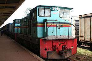
- Loco from Uganda with small air brake hose above coupling and tap.
 Greece NG Air Brake
Thin hose above and tap
See also
Manufacturers
- Westinghouse Air Brake Company (WABCO), later Wabtec, United States
- Faiveley Transport, France[15]
- Knorr-Bremse Rail Vehicle Systems, Germany
- Westinghouse Brake and Signal Company Ltd (now a division of Knorr-Bremse), UK
- New York Air Brake (now a division of Knorr-Bremse), United States
- MZT HEPOS, Macedonia[16](now a division of Wabtec)
- Mitsubishi Electric, Japan
- Nabtesco, Japan[17]
- Dellner, Sweden[18]
- Aflink, South Africa[19]
- Hanning & Kahl GmbH LRT trains, Hydraulic Brakes and control components, Germany [14]
- Voith, Germany[20]
- YUJIN Machinery Ltd, South Korea[21]
References
- ↑ T E Harrison (Chief Engineer of the North Eastern Railway at the time, document of December 1877 quoted (page 193) in F.A.S.Brown Great Northern Railway Engineers Volume One: 1846–1881, George Allen & Unwin, London, 1966: (for those who feel the Victorians should have metric conversions backfitted: at speeds of 45.5 miles per hour (73.2 km/h) - 48.5 miles per hour (78.1 km/h) stopping distances were 800 yards (730 m) - 1,200 yards (1,100 m))
- ↑ , Report of the Court of Inquiry into the Circumstances Attending the Double Collision on the Great Northern Railway which occurred at Abbotts Ripton on the 21st January 1876, HMSO, 1876
- ↑ According to (C) Hamilton Ellis, Nineteenth Century Railway Carriages, Modern Transport, London, 1949 The Midland supplied both the hydraulic-braked trains trialed at Newark (see below) Ellis goes on to note op cit p 58
Freezing possibilities told against the hydraulic brakes, though the Great Eastern Railway, which used them for a while, overcame this by the use of salt water
- ↑ "Welcome to Saskrailmuseum.org". Contact Us. September 11, 2008. Retrieved October 3, 2008.
- ↑ A "simple" vacuum brake, with no fail-safe capability, invented by James Young Smith, in the U.S. Simmons, Jack; Biddle, Gordon (1997). The Oxford Companion to British Railway History. Oxford, England: Oxford University Press. p. 42. ISBN 978-0-19-211697-0.
- ↑ data below from (C) Hamilton Ellis, Nineteenth Century Railway Carriages, Modern Transport, London, 1949 - ranked in order of merit after allowing for weight of train - italicised systems were not truly continuous
- ↑ simplicity of engineering as a technical reason; but there seem to have been strong non-technical reasons to do with Westinghouse's salesmanship
- ↑ Railway Magazine March 1952 p. 210
- ↑ Railway Magazine March 1952 p. 145
- ↑ http://nla.gov.au/nla.news-article5947355#reloadOnBack
- ↑ (Cc) Glossary for the LNWR Society
- ↑ Huffstutter, P.J. (8 July 2013). "Insight: How a train ran away and devastated a Canadian town". Reuters. Retrieved 9 July 2013.
- ↑ "DR Congo crash toll 'passes 100'". BBC News. August 2, 2007. Retrieved May 22, 2010.
- 1 2 Hanning & Kahl
- ↑ Faiveley Transport
- ↑ MZT Hepos
- ↑ Nabtesco
- ↑ https://web.archive.org/web/20090520005347/http://www.railway-technology.com/contractors/brakes/dellner/enquiry.asp. Archived from the original on May 20, 2009. Retrieved February 24, 2009. Missing or empty
|title=(help)— - ↑ http://www.aflink.co.za/Rail/rail.html
- ↑ Voith
- ↑ Yujin Machinery
Sources
- British Transport Commission, London (1957:142). Handbook for Railway Steam Locomotive Enginemen
Further reading
- Marsh, G.H. and Sharpe, A.C. The development of railway brakes. Part 1 1730-1880 Railway engineering journal 2(1) 1973, 46-53; Part 2 1880-1940 Railway engineering journal 2(2) 1973, 32-42
- Winship, I.R. The acceptance of continuous brakes on railways in Britain History of technology 11 1986, 209-248. Covering developments from about 1850 to 1900.
External links
| Wikimedia Commons has media related to Railway brakes. |