Solenoid valve

A solenoid valve is an electromechanically operated valve. The valve is controlled by an electric current through a solenoid: in the case of a two-port valve the flow is switched on or off; in the case of a three-port valve, the outflow is switched between the two outlet ports. Multiple solenoid valves can be placed together on a manifold.
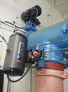
Solenoid valves are the most frequently used control elements in fluidics. Their tasks are to shut off, release, dose, distribute or mix fluids. They are found in many application areas. Solenoids offer fast and safe switching, high reliability, long service life, good medium compatibility of the materials used, low control power and compact design.
Besides the plunger-type actuator which is used most frequently, pivoted-armature actuators and rocker actuators are also used.
Operation
There are many valve design variations. Ordinary valves can have many ports and fluid paths. A 2-way valve, for example, has 2 ports; if the valve is open, then the two ports are connected and fluid may flow between the ports; if the valve is closed, then ports are isolated. If the valve is open when the solenoid is not energized, then the valve is termed normally open (N.O.). Similarly, if the valve is closed when the solenoid is not energized, then the valve is termed normally closed.[1] There are also 3-way and more complicated designs.[2] A 3-way valve has 3 ports; it connects one port to either of the two other ports (typically a supply port and an exhaust port).
Solenoid valves are also characterized by how they operate. A small solenoid can generate a limited force. If that force is sufficient to open and close the valve, then a direct acting solenoid valve is possible. An approximate relationship between the required solenoid force Fs, the fluid pressure P, and the orifice area A for a direct acting solenoid value is:[3]

Where d is the orifice diameter. A typical solenoid force might be 15 N (3.4 lbf). An application might be a low pressure (e.g., 10 psi (69 kPa)) gas with a small orifice diameter (e.g., 3⁄8 in (9.5 mm) for an orifice area of 0.11 in2 (7.1×10⁻⁵ m2) and approximate force of 1.1 lbf (4.9 N)).
When high pressures and large orifices are encountered, then high forces are required. To generate those forces, an internally piloted solenoid valve design may be possible.[1] In such a design, the line pressure is used to generate the high valve forces; a small solenoid controls how the line pressure is used. Internally piloted valves are used in dishwashers and irrigation systems where the fluid is water, the pressure might be 80 pounds per square inch (550 kPa) and the orifice diameter might be 3⁄4 in (19 mm).
In some solenoid valves the solenoid acts directly on the main valve. Others use a small, complete solenoid valve, known as a pilot, to actuate a larger valve. While the second type is actually a solenoid valve combined with a pneumatically actuated valve, they are sold and packaged as a single unit referred to as a solenoid valve. Piloted valves require much less power to control, but they are noticeably slower. Piloted solenoids usually need full power at all times to open and stay open, where a direct acting solenoid may only need full power for a short period of time to open it, and only low power to hold it.
A direct acting solenoid valve typically operates in 5 to 10 milliseconds. The operation time of a piloted valve depends on its size; typical values are 15 to 150 milliseconds.[4]
Power consumption and supply requirements of the solenoid vary with application, being primarily determined by fluid pressure and line diameter. For example, a popular 3/4" 150 psi sprinkler valve, intended for 24 VAC (50 - 60 Hz) residential systems, has a momentary inrush of 7.2 VA, and a holding power requirement of 4.6 VA.[5] Comparatively, an industrial 1/2" 10000 psi valve, intended for 12, 24, or 120 VAC systems in high pressure fluid and cryogenic applications, has an inrush of 300 VA and a holding power of 22 VA.[6] Neither valve lists a minimum pressure required to remain closed in the un-powered state.
Internally piloted
While there are multiple design variants, the following is a detailed breakdown of a typical solenoid valve design.
A solenoid valve has two main parts: the solenoid and the valve. The solenoid converts electrical energy into mechanical energy which, in turn, opens or closes the valve mechanically. A direct acting valve has only a small flow circuit, shown within section E of this diagram (this section is mentioned below as a pilot valve). In this example, a diaphragm piloted valve multiplies this small pilot flow, by using it to control the flow through a much larger orifice.
Solenoid valves may use metal seals or rubber seals, and may also have electrical interfaces to allow for easy control. A spring may be used to hold the valve opened (normally open) or closed (normally closed) while the valve is not activated.

B- Diaphragm
C- Pressure chamber
D- Pressure relief passage
E- Electro Mechanical Solenoid
F- Output side
The diagram to the right shows the design of a basic valve, controlling the flow of water in this example. At the top figure is the valve in its closed state. The water under pressure enters at A. B is an elastic diaphragm and above it is a weak spring pushing it down. The diaphragm has a pinhole through its center which allows a very small amount of water to flow through it. This water fills the cavity C on the other side of the diaphragm so that pressure is equal on both sides of the diaphragm, however the compressed spring supplies a net downward force. The spring is weak and is only able to close the inlet because water pressure is equalized on both sides of the diaphragm.
Once the diaphragm closes the valve, the pressure on the outlet side of its bottom is reduced, and the greater pressure above holds it even more firmly closed. Thus, the spring is irrelevant to holding the valve closed.
The above all works because the small drain passage D was blocked by a pin which is the armature of the solenoid E and which is pushed down by a spring. If current is passed through the solenoid, the pin is withdrawn via magnetic force, and the water in chamber C drains out the passage D faster than the pinhole can refill it. The pressure in chamber C drops and the incoming pressure lifts the diaphragm, thus opening the main valve. Water now flows directly from A to F.
When the solenoid is again deactivated and the passage D is closed again, the spring needs very little force to push the diaphragm down again and the main valve closes. In practice there is often no separate spring; the elastomer diaphragm is molded so that it functions as its own spring, preferring to be in the closed shape.
From this explanation it can be seen that this type of valve relies on a differential of pressure between input and output as the pressure at the input must always be greater than the pressure at the output for it to work. Should the pressure at the output, for any reason, rise above that of the input then the valve would open regardless of the state of the solenoid and pilot valve.
Components
Solenoid valve designs have many variations and challenges.
Common components of a solenoid valve:[7][8][9][10]
- Solenoid subassembly
- Retaining clip (a.k.a. coil clip)
- Solenoid coil (with magnetic return path)
- Core tube (a.k.a. armature tube, plunger tube, solenoid valve tube, sleeve, guide assembly)
- Plugnut (a.k.a. fixed core)
- Shading coil (a.k.a. shading ring)
- Core spring (a.k.a. counter spring)
- Core (a.k.a. plunger, armature)
- Core tube–bonnet seal
- Bonnet (a.k.a. cover)
- Bonnet–diaphram–body seal
- Hanger spring
- Backup washer
- Diaphragm
- Bleed hole
- Disk
- Valve body
- Seat
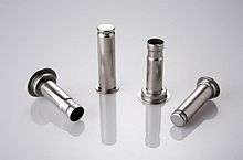
The core or plunger is the magnetic component that moves when the solenoid is energized. The core is coaxial with the solenoid. The core's movement will make or break the seals that control the movement of the fluid. When the coil is not energized, springs will hold the core in its normal position.
The plugnut is also coaxial.
The core tube contains and guides the core. It also retains the plugnut and may seal the fluid. To optimize the movement of the core, the core tube needs to be nonmagnetic. If the core tube were magnetic, then it would offer a shunt path for the field lines.[11] In some designs, the core tube is an enclosed metal shell produced by deep drawing. Such a design simplifies the sealing problems because the fluid cannot escape from the enclosure, but the design also increases the magnetic path resistance because the magnetic path must traverse the thickness of the core tube twice: once near the plugnut and once near the core. In some other designs, the core tube is not closed but rather an open tube that slips over one end of the plugnut. To retain the plugnut, the tube might be crimped to the plugnut. An O-ring seal between the tube and the plugnut will prevent the fluid from escaping.
The solenoid coil consists of many turns of copper wire that surround the core tube and induce the movement of the core. The coil is often encapsulated in epoxy. The coil also has an iron frame that provides a low magnetic path resistance.
Materials
The valve body must be compatible with the fluid; common materials are brass, stainless steel, aluminum, and plastic.[12]
The seals must be compatible with the fluid.
To simplify the sealing issues, the plugnut, core, springs, shading ring, and other components are often exposed to the fluid, so they must be compatible as well. The requirements present some special problems. The core tube needs to be non-magnetic to pass the solenoid's field through to the plugnut and the core. The plugnut and core need a material with good magnetic properties such as iron, but iron is prone to corrosion. Stainless steels can be used because they come in both magnetic and non-magnetic varieties.[13] For example, a solenoid valve might use 304 stainless steel for the body, 305 stainless steel for the core tube, 302 stainless steel for the springs, and 430 F stainless steel (a magnetic stainless steel[14]) for the core and plugnut.[15]
Types
Many variations are possible on the basic, one-way, one-solenoid valve described above:
- one- or two-solenoid valves;
- direct current or alternating current powered;
- different number of ways and positions;
Common uses
Solenoid valves are used in fluid power pneumatic and hydraulic systems, to control cylinders, fluid power motors or larger industrial valves. Automatic irrigation sprinkler systems also use solenoid valves with an automatic controller. Domestic washing machines and dishwashers use solenoid valves to control water entry into the machine. Solenoid valves are used in the paintball industry, solenoid valves are usually referred to simply as "solenoids." They are commonly used to control a larger valve used to control the propellant In addition to this, these valves are now being used in household water purifiers.
Solenoid valves can be used for a wide array of industrial applications, including general on-off control, calibration and test stands, pilot plant control loops, process control systems, and various original equipment manufacturer applications. [16]
History and commercial development
In 1910, ASCO Numatics became the first company to develop and manufacture the solenoid valve.[17][18]
See also
References
- 1 2 ASCO http://www.controlandpower.com/catalog/PDFs/ASCO/ASCO%2035-1%20General%20Service%202-Way%20Valves.pdf
- ↑ ASCO, Engineering Information: Solenoid Valves, http://www.controlandpower.com/catalog/PDFs/ASCO/ASCO%2035-9%20Engineering%20Information.pdf p. 448
- ↑ https://www.asconumatics.eu/images/site/upload/_en/pdf1/00022gb.pdf p. V030-1; the relation ignores the dynamic head.
- ↑ ASCO http://www.controlandpower.com/catalog/PDFs/ASCO/ASCO%2035-9%20Engineering%20Information.pdf p 454
- ↑ "Orbit 3/4 150 PSI Sprinkler" (PDF). homedepot. Home Depot. Retrieved 12/9/2015. Check date values in:
|access-date=(help) - ↑ "Omega High Pressure Solenoid Valve SVH-111/SVH-112 Series" (PDF). omega. Omega. Retrieved 12/9/2015. Check date values in:
|access-date=(help) - ↑ http://www.controlandpower.com/catalog/PDFs/ASCO/ASCO%2035-0%20Valve%20Terminology.pdf p. xv
- ↑ http://www.sirai.com/inglese/serieV/parti.php Illustration showing parts of solenoid valve. Warning: illustration does not show any space for plunger travel.
- ↑ http://www.sirai.com/inglese/serieD/parti.php Illustration showing parts of solenoid value. Warning: illustration does not show any space for plunger travel.
- ↑ http://www.mgacontrols.com/2011/02/24/mm-international-solenoid-valves/
- ↑ Skinner Valve 1997, p. 128, stating "The tube is made of non-magnetic material to make certain that the flux is directed through the plunger rather than around it."
- ↑ Skinner Valve (1997), Two-Way, Three-Way and Four-Way Solenoid Valves (PDF), Parker Hannifin, Catalog CFL00897, p. 128
- ↑ http://www.controlandpower.com/catalog/PDFs/ASCO/ASCO%2035-9%20Engineering%20Information.pdf page 450f states, "Internal parts in contact with fluids are of non-magnetic 300 and magnetic 400 series stainless steel."
- ↑ http://www.matweb.com/search/datasheettext.aspx?matguid=d1fcb0f0cca340a4aa9068d6af5e6606
- ↑ ASCO 8210, p. 11, http://www.controlandpower.com/catalog/PDFs/ASCO/ASCO%2035-1%20General%20Service%202-Way%20Valves.pdf
- ↑ http://www.valcor.com/scientific-and-industrial/general-purpose-solenoid-valves/
- ↑ Trauthwein, Greg (February 2006). "Propelling W&O Supply to New Heights". Maritime Reporter.
- ↑ Valve Products, a Huge History About Valves "A History of ASCO" Check
|url=value (help). Retrieved 2013-06-11.
External links
- http://www.mgacontrols.com/category/solenoid-valves/ illustrations of 2-way, 3-way, and pilot operated solenoid valves
- http://www.maritime.org/doc/fleetsub/refrig/chap7.htm pp. 39–40. Solenoid valve illustration; breakaway pin / kick-off.
- http://www.smc.eu/portal/WebContent/local/UK/Pneu_Book/Solenoid_Valves.jsp Skinner valve, 1930s; magnetic path issues; wear; power; number of cycles
- http://www.surmaq.com/html/cata/parker/contr/skinner.pdf pp. 128-131; tech details of design; different terminology; welded sleeve; valve sizing. Page 128: "Skinner Valve plunger assemblies, when appropriate, use floating top and bottom seals to enhance valve performance. Floating seals permit the plunger to generate a larger actuation force to open against the pressure differential in the valve. This enables the valve to operate at higher pressure ratings." Material has implications for shading ring: copper is satisfactory for many materials, but it is unsatisfactory for coffee and urea; silver is satisfactory for those fluids. (pp 130–131.)
- http://www.processindustryforum.com/article/answers-technical-questions-solenoid-valves-pressure-operated-valves different technologies of solenoid valves explanation
Shaded coil
- http://cr4.globalspec.com/thread/56783/Shading-Ring discussion about shading coil
- Design of Shading Coils for Minimizing the Contact Bouncing of AC Contactors, doi:10.1109/HOLM.2008.ECP.34
- http://everything2.com/title/Shading+ring
- https://www.asconumatics.eu/images/site/upload/_en/pdf1/00022gb.pdf More detailing information about solenoid and shading coil
- http://relays.te.com/schrack/pdf/C0_v4bg_5.pdf About relay design but includes relevant information