Solid Edge
|
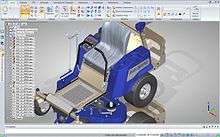
Solid Edge screen | |
| Developer(s) | Siemens PLM Software |
|---|---|
| Initial release | 1995 |
| Stable release |
Solid Edge ST9
/ May 2016 |
| Operating system | 7/8/10 |
| Type | CAD software |
| License | Proprietary |
| Website |
www |
Solid Edge is a 3D CAD, parametric feature (history based) and synchronous technology solid modeling software. It runs on Microsoft Windows and provides solid modeling, assembly modelling and 2D orthographic view functionality for mechanical designers. Through third party applications it has links to many other Product Lifecycle Management (PLM) technologies.
Originally developed and released by Intergraph in 1996 using the ACIS geometric modeling kernel it later changed to using the Parasolid kernel. In 1998 it was purchased and further developed by UGS Corp (the purchase date corresponds to the kernel swap).
In 2007, UGS was acquired by the Automation & Drives Division of Siemens AG. UGS company was renamed Siemens PLM Software on October 1, 2007. Since Sep 2006 Siemens also offers a free 2D version called Solid Edge 2D Drafting.
Solid Edge is available in either Classic or Premium. The "Premium" package includes all of the features of "Classic" in addition to mechanical and electrical routing software, and powerful engineering simulation capabilities for CAE (Computer Aided Engineering). [1]
Solid Edge is a direct competitor to SolidWorks, PTC Creo, and Autodesk Inventor.
History
- Solid Edge 1 1995 (first release)
- Solid Edge 2 1996
- Solid Edge 3 1996
- Solid Edge 3.5 1997 (In October 1997 the Sheet Metal environment was introduced)
- Solid Edge 4 1997
- Solid Edge 5 1998 (UGS Corp switched from the ACIS modeling kernel to Parasolid kernel)
- Solid Edge 6
- Solid Edge 7
- Solid Edge 8
- Solid Edge 9
- Solid Edge 10
- Solid Edge 11
- Solid Edge 12
- Solid Edge 14
- Solid Edge 15
- Solid Edge 16 2004
- Solid Edge 17 2005
- Solid Edge 18 2006
- Solid Edge 19 2007
- Solid Edge 20 2008
- Solid Edge ST1 2008 with Synchronous Technology
- Solid Edge ST2 2009
- Solid Edge ST3 2010 (was released on October 13, allowing both Synchronous and Ordered mode to exist in all modelling environment).
- Solid Edge ST4 2011
- Solid Edge ST5 2012
- Solid Edge ST6 2013
- Solid Edge ST7 2014 (older Virtual Studio renderer replaced with Keyshot; 64-bit only)
- Solid Edge ST8 2015[2]
- Solid Edge ST9 2016 (enhanced cloud-integration)[3]
Modeling
Ordered
The ordered modeling process begins with a base feature controlled by a 2D sketch, which is either a linear, revolved, lofted, or swept extrusion. Each subsequent feature is built on the previous feature. When editing, the model is "rolled back" to the point where the feature was created so that the user cannot try to apply constraints to geometry that does not yet exist. The drawback is that the user does not see how the edit will interact with the subsequent features. This is typically called "history" or "regeneration based" modeling. In both ordered and synchronous mode Solid Edge offers very powerful, easy yet stable modeling in hybrid surface/solid mode, where "Rapid Blue" technology helps the user to create complex shapes in an intuitive and easy way.
Direct
The Direct modeling features allows the user to change model geometry/topology without being hindered by a native model's existing—or an imported model's lack of—parametric and/or history data. This is particularly useful for working with imported models or complex native models. Direct modeling features are available in both Ordered and Synchronous mode. If used in the Ordered mode, the direct modeling edits are appended to the history tree at the point of current rollback just like any other ordered feature.
Synchronous
The software combines direct modeling with dimension driven design (features and synchronously solving parametrics) under the name "Synchronous Technology". Parametric relationships can be applied directly to the solid features without having to depend on 2D sketch geometry, and common parametric relationships are applied automatically.
Unlike other direct modeling systems, it is not driven by the typical history-based modeling system, instead providing parametric dimension-driven modeling by synchronizing geometry, parameters and rules using a decision-making engine, allowing users to apply unpredicted changes. This object-driven editing model is known as the Object Action Interface, which emphasizes a User Interface that provides Direct Manipulation of objects (DMUI). ST2 added support for sheet metal designing, and also recognizing bends, folds and other features of imported sheet metal parts.
Synchronous Technology has been integrated into Solid Edge and another Siemens commercial CAD software, NX, as an application layer built on the D-Cubed and Parasolid software components.
Assembly
An assembly is built from individual part documents connected by mating constraints, as well as assembly features and directed parts like frames which only exist in the Assembly context. Solid Edge supports large assemblies with over 1,000,000 parts.

Features
A draft file consists of the 3D model projected to one or more 2D views of a part or assembly file.
Solid Edge integrates with Sharepoint and Teamcenter to provide product lifecycle management. Solid Edge also integrates with PLM products from third parties.
Solid Edge provides support for Finite Element Analysis (FEA) starting with Solid Edge ST2 version released in 2009. This functionality is based on Siemens PLM's existing Femap and NX Nastran technologies.
See also
References
- ↑ "Solid Edge". Structures.Aero. SDA. Retrieved 14 July 2015.
- ↑ "Siemens Releases Solid Edge ST8". TenLinks. Retrieved 20 August 2015.
- ↑ "Siemens Releases Solid Edge ST9". ENGINEERING.com. Retrieved 26 May 2016.
External links
| Wikimedia Commons has media related to Solid Edge. |