Split-phase electric power
A split-phase or single-phase three-wire system is a type of single-phase electric power distribution. It is the AC equivalent of the original Edison three-wire direct-current system. Its primary advantage is that it saves conductor material over a single-ended single-phase system, while only requiring single phase on the supply side of the distribution transformer.[1]
Connections

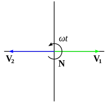
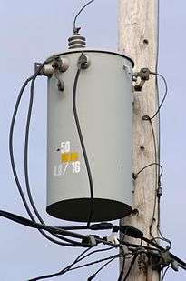
A transformer supplying a three-wire distribution system has a single-phase input (primary) winding. The output (secondary) winding is center-tapped and the center tap connected to a grounded neutral. As shown in Fig. 1. either end to center has half the voltage of end-to-end. Fig. 2 illustrates the phasor diagram of the output voltages for a split-phase transformer. Since the two phasors do not define a unique direction of rotation for a revolving magnetic field, a split single-phase is not a two-phase system.
In the United States, the practice originated with the DC distribution system developed by Thomas Edison. By dividing a lighting load into two equal groups of lamps connected in series, the total supply voltage can be doubled and the size of conductors reduced substantially.
The line to ground voltage is half the line-to-line voltage. Lighting and small appliances are connected between a line wire and the neutral. Large appliances, such as cooking equipment, space heating, water pumps, clothes dryers, and air conditioners are connected across the two line conductors, requiring less current and smaller conductors than would be needed if the appliances were designed for the lower voltage. [2]
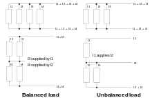
If the load were guaranteed to be balanced, then the neutral conductor would not carry any current and the system would be equivalent to a single-ended system of twice the voltage with the line wires taking half the current. This would not need a neutral conductor at all, but would be wildly impractical for varying loads; just connecting the groups in series would result in excessive voltage and brightness variation as lamps are switched on and off.
By connecting the two lamp groups to a neutral, intermediate in potential between the two live legs, any imbalance of the load will be supplied by a current in the neutral, giving substantially constant voltage across both groups. The total current carried in all three wires (including the neutral) will always be twice the supply current of the most heavily loaded half.
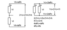
For short wiring runs limited by conductor ampacity, this allows three half-sized conductors to be substituted for two full-sized ones, using 75% of the copper of an equivalent single-phase system.
Longer wiring runs are more limited by voltage drop in the conductors. Because the supply voltage is doubled, a balanced load can tolerate double the voltage drop, allowing quarter-sized conductors to be used; this uses 3/8 the copper of an equivalent single-phase system.
In practice, some intermediate value is chosen. For example, if the imbalance is limited to 25% of the total load (half of one half) rather than the absolute worst-case 50%, then conductors 3/8 of the single-phase size will guarantee the same maximum voltage drop, totalling 9/8 of one single-phase conductor, 56% of the copper of the two single-phase conductors.
Technical power (balanced power)
In a so-called technical power system, an isolation transformer with a center tap is used to create a separate supply with conductors at a balanced 60 V with respect to ground. The purpose of a balanced power system is to minimize the noise coupled into sensitive equipment from the power supply.
Unlike a three-wire distribution system, the grounded neutral is not distributed to the loads; only line-to-line connections at 120 V are used. A balanced power system is only used for specialized distribution in audio and video production studios, sound and television broadcasting, and installations of sensitive scientific instruments.
The U.S. National Electrical Code provides rules for technical power installations.[3] The systems are not to be used for general-purpose lighting or other equipment, and may use special sockets to ensure only approved equipment is connected to the system. Additionally, technical power systems pay special attention to the way the distribution system is grounded.
Applications
Europe
In Europe, three-phase 230/400 V is most commonly used. However, 230/460 V, three-wire, single-phase systems are used to run farms and small groups of houses when only one (or sometimes two) of the three-phase high-voltage conductors are available.
In the UK, electric tools and portable lighting at construction sites are required to be fed from a centre-tapped system with only 55 V between live conductors and the earth. This system is used with 110 V equipment and therefore no neutral conductor is needed. The intention is to reduce the electrocution hazard that may exist when using electrical equipment at a wet or outdoor construction site. Portable isolating transformers that transform single-phase 230 V to this 110 V system are a common piece of construction equipment. Generator sets used for construction sites are equipped to supply it directly.
An incidental benefit was that the filaments of 110 V incandescent lamps used on such systems are thicker and therefore mechanically more rugged than 230 V lamps.
Oceania
In Australia and New Zealand, remote loads are connected to the grid using SWER (single-wire earth return) transmission lines, since it is cheapest to run only one wire. The primary of the transformer is connected between the high voltage line and earth, the secondary is a three-wire single-phase system as described here, the secondary voltage being 230/460 V. Single phase loads are split between the two circuits. Hot water services use both circuits.
North America
This three-wire system is common in countries with a standard phase-neutral voltage of 120 V. It is commonly used in North America for light commercial applications.[2]
In North American electrical codes, the split-phase distribution may be carried to the outlet receptacles. Two 120 volt devices may be plugged into a duplex receptacle that connects one neutral wire to both outlets. This saves the cost of one wire back to the panelboard. Such multiwire branch circuits have special rules in the electrical codes to ensure they are safely applied.
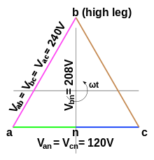
A variation is the 240 V delta 4-wire system, also known as a high-leg or red-leg delta. This is a three-phase 240 V delta connected system, in which one winding of the transformer has a center tap which is connected to ground and used as the system neutral. This allows a single service to supply 120 V for lighting, 240 V single-phase for heating appliances, and 240 V three-phase for motor loads (such as air conditioning compressors). Two of the phases are 120 V to neutral, the third phase or "high leg" is 208 V to neutral.
Multiwire systems split more than two ways are possible with both AC and DC but have the significant disadvantage that no matter which point is tied to ground some of the wires will have a higher earth relative voltage than the utilisation voltage; therefore, such systems are not used in normal power distribution.
Railways
In Sweden split-phase electric power is also used on some railways. The center tap is grounded, one pole is fed with an overhead wire section, while the other wire is used for another section.
Amtrak's 60 Hz traction power system in the Northeast Corridor between New York and Boston also uses split-phase power distribution. Two separate wires are run along the track, the contact wire for the locomotive and an electrically separate feeder wire. Each wire is fed with 25 kV with respect to ground, with 50 kV between them. Autotransformers along the track balance the loads between the contact and feeder wires, reducing resistive losses.
In the UK Network Rail are using autotransformers on all new 50 Hz electrification, and (as of 2014) are converting many old booster transformer installations to autotransformers, to reduce energy losses and exported electromagnetic interference, both of which increase when longer, heavier, or faster trains are introduced, drawing higher peak current from the supply. Note that booster transformers only "boost" the return of traction current through its intended path, the "return conductor", rather than randomly through the earth, and do not boost, but rather reduce, the available voltage at the train, and introduce additional losses. The autotransformer system enforces the traction return current taking its intended path, while reducing the transmission losses, and therefore achieves both required objectives, of controlling return current leakage to earth and ensuring low energy loss, simultaneously. There is an initial cost penalty, because the previous return conductor, insulated to a fairly modest voltage, must be replaced by an anti-phase feeder, insulated to 25 kV, and the autotransformers transformers themselves are larger and more expensive than the previous booster transformers.
See also
References
- ↑ Terrell Croft and Wilford Summers (ed), American Electricians' Handbook, Eleventh Edition, McGraw Hill, New York (1987) ISBN 0-07-013932-6, chapter 3, pages 3-10, 3-14 to 3-22.
- 1 2 Gonen, Turan. Electric Power Distribution System Engineering, 2nd ed. CRC Press, 2007, p. 284.
- ↑ NFPA 70, National Electrical Code 2005, National Fire Protection Association, Inc., Quincy, Massachusetts USA, (2005). no ISBN , articles 640 and 647