Submarine pipeline
A submarine pipeline (also known as marine, subsea or offshore pipeline) is a pipeline that is laid on the seabed or below it inside a trench.[1][2] In some cases, the pipeline is mostly on-land but in places it crosses water expanses, such as small seas, straights and rivers.[3] Submarine pipelines are used primarily to carry oil or gas, but transportation of water is also important.[3] A distinction is sometimes made between a flowline and a pipeline.[1][3][4] The former is an intrafield pipeline, in the sense that it is used to connect subsea wellheads, manifolds and the platform within a particular development field. The latter, sometimes referred to as an export pipeline, is used to bring the resource to shore.[1] Sizeable pipeline construction projects need to take into account a large number of factors, such as the offshore ecology, geohazards and environmental loading – they are often undertaken by multidisciplinary, international teams.[1]
Route selection
One of the earliest and most critical tasks in a submarine pipeline planning exercise is the route selection.[5] This selection has to consider a variety of issues, some of a political nature, but most others dealing with geohazards, physical factors along the prospective route, and other uses of the seabed in the area considered.[5][6] This task begins with a fact-finding exercise, which is a standard desk study that includes a survey of geological maps, bathymetry, fishing charts, aerial and satellite photography, as well as information from navigation authorities.[5][6]
Physical factors
The primary physical factor to be considered in submarine pipeline construction is the state of the seabed – whether it is smooth (i.e., relatively flat) or uneven (corrugated, with high points and low points). If it is uneven, the pipeline will include free spans when it connects two high points, leaving the section in between unsupported.[2][7] If an unsupported section is too long, the bending stress exerted onto it (due to its weight) may be excessive. Vibration from current-induced vortexes may also become an issue.[7][8] Corrective measures for unsupported pipeline spans include seabed leveling and post-installation support, such as berm or sand infilling below the pipeline. The strength of the seabed is another significant parameter. If the soil is not strong enough, the pipeline may sink into it to an extent where inspection, maintenance procedures and prospective tie-ins become difficult to carry out. At the other extreme, a rocky seabed is expensive to trench and, at high points, abrasion and damage of the pipeline's external coating may occur.[7][8] Ideally, the soil should be such as to allow the pipe to settle into it to some extent, thereby providing it with some lateral stability.[7]

Other physical factors to be taken into account prior to building a pipeline include the following:[2][7][8][9][10]
- Seabed mobility: Sandwaves and megaripples are features that move with time, such that a pipeline that was supported by the crest of one such feature during construction may find itself in a trough later during the pipeline's operational lifespan. The evolution of these features is difficult to predict so it is preferable to avoid the areas where they are known to exist.
- Submarine landslides: They result from high sedimentation rates and occur on steeper slopes. They can be triggered by earthquakes. When the soil around the pipe is subjected to a slide, especially if the resulting displacement is at high angle to the line, the pipe within it can incur severe bending and consequent tensile failure.
- Currents: High currents are objectionable in that they hinder pipe laying operations. For instance, in shallow seas tidal currents may be quite strong in a strait between two islands. Under these circumstances, it may be preferable to bring the pipe elsewhere, even if this alternative route ends up being longer.
- Waves: In shallow waters, waves can also be problematic for pipeline laying operations (in severe wave regimes) and, subsequently, to its stability, because of the water's scouring action. This is one of a number of reasons why landfalls (where the pipeline reaches the shoreline) are particularly delicate areas to plan.
- Ice-related issues: In freezing waters, floating ice features often drift into shallower waters, and their keel comes into contact with the seabed. As they continue to drift, they gouge the seabed and can hit the pipeline.[11] Stamukhi can also damage this structure, either by exerting high local stresses on it or by causing to soil around it to fail, thereby inducing excessive bending. Strudel are another pipeline hazard in cold waters – water gushing through them can remove the soil from below the structure, making it vulnerable to overstress (due to self-weight) or vortex-induced oscillations. Pipeline route planning for areas where these risks are known to exist has to consider laying the pipeline in a back-filled trench.
Other uses of the seabed
Proper planning of a pipeline route has to factor in a wide range of human activities that make use of the seabed along the proposed route, or that are likely to do so in the future. They include the following:[2][8][12]
- Other pipelines: If and where the proposed pipeline intersects an existing one, which is not uncommon, a bridging structure may be required at that juncture in order to cross it. This has to be done at a right angle. The juncture should be carefully designed so as to avoid interferences between the two structures either by direct physical contact or due to hydrodynamic effects.
- Fishing vessels: Commercial fishing makes use of heavy fishing nets dragged on the seabed and extending several kilometers behind the trawler. This net could snag the pipeline, with potential damage to both pipeline and vessel.
- Ship anchors: Ship anchors are a potential threat to pipelines, especially near harbors.
- Military activities: Some areas still have mines originating from former conflicts but that are still operational. Other areas, used for bombing or gunning practices, may also conceal live ammunition. Moreover, at some locations, various types of instrumentation are laid on the seafloor for submarine detection. These areas have to be avoided.
Submarine pipeline characteristics
Submarine pipelines generally vary in diameter from 3 inches (76 mm) for gas lines, to 72 inches (1,800 mm) for high capacity lines.[1][2] Wall thicknesses typically range from 10 millimetres (0.39 in) to 75 millimetres (3.0 in). The pipe can be designed for fluids at high temperature and pressure. The walls are made from high-yield strength steel, 350-500 MPa (50,000-70,000 psi), weldability being one of the main selection criteria.[2] The structure is often shielded against external corrosion by coatings such as bitumastic or epoxy, supplemented by cathodic protection with sacrificial anodes.[2][13] Concrete or fiberglass wrapping provides further protection against abrasion. The addition of a concrete coating is also useful to compensate for the pipeline's negative buoyancy when it carries lower density substances.[2][14]
The pipeline's inside wall is not coated for petroleum service. But when it carries seawater or corrosive substances, it can be coated with epoxy, polyurethane or polyethylene; it can also be cement-lined.[2][13] In the petroleum industry, where leaks are unacceptable and the pipelines are subject to internal pressures typically in the order of 10 MPa (1500 psi), the segments are joined by full penetration welds.[2][13] Mechanical joints are also used. A pig is a standard device in pipeline transport, be it on-land or offshore. It is used to test for hydrostatic pressure, to check for dents and crimps on the sidewalls inside the pipe, and to conduct periodic cleaning and minor repairs.[1][2]
Pipeline construction
Pipeline construction involves two procedures: assembling a large number of pipe segments into a full line, and installing that line along the desired route. Several systems can be used – for a submarine pipeline, the choice in favor of any one of them is based on the following factors: physical and environmental conditions (e.g. currents, wave regime), availability of equipment and costs, water depth, pipeline length and diameter, constraints tied to the presence of other lines and structures along the route.[2] These systems are generally divided into four broad categories: pull/tow, S-lay, J-lay and reel-lay.[15][16][17][18]
The pull/tow system
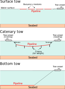
In the pull/tow system, the submarine pipeline is assembled onshore and then towed to location. Assembly is done either parallel or perpendicular to the shoreline – in the former case, the full line can be built prior to tow out and installation.[19] A significant advantage with the pull/tow system is that pre-testing and inspection of the line are done onshore, not at sea.[19] It allows to handle lines of any size and complexity.[17][20] As for the towing procedures, a number of configurations can be used, which may be categorized as follows: surface tow, near-surface tow, mid-depth tow and off-bottom tow.[21]
- Surface tow: In this configuration, the pipeline remains at the surface of the water during tow, and is then sunk into position at lay site. The line has to be buoyant – this can be done with individual buoyancy units attached to it.[19] Surface tows are not appropriate for rough seas and are vulnerable to lateral currents.
- Near-surface tow: The pipeline remains below the water surface but close to it – this mitigates wave action. But the spar buoys used to maintain the line at that level are affected by rough seas, which in itself may represent a challenge for the towing operation.
- Mid-depth tow: The pipeline is not buoyant – either because it is heavy or it is weighted down by hanging chains. In this configuration, the line is suspended in a catenary between two towing vessels. The shape of that catenary (the sag) is a balance between the line's weight, the tension applied to it by the vessels and hydrodynamic lift on the chains.[22] The amount of allowable sag is limited by how far down the seabed is.
- Off-bottom tow: This configuration is similar to the mid-depth tow, but here the line is maintained within 1 to 2 m (several feet) away from the bottom, using chains dragging on the seabed.
- Bottom tow: In this case, the pipeline is dragged onto the bottom – the line is not affected by waves and currents, and if the sea gets too rough for the tow vessel, the line can simply be abandoned and recovered later. Challenges with this type of system include: requirement for an abrasion-resistant coating, interaction with other submarine pipelines and potential obstructions (reef, boulders, etc.). Bottom tow is commonly used for river crossings and crossings between shores.[23]
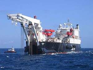
The S-lay system
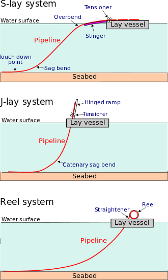
In the S-lay system, the pipeline assembly is done at the installation site, on board a vessel that has all the equipment required for joining the pipe segments: pipe handling conveyors, welding stations, X-ray equipment, joint-coating module, etc.[24] The S notation refers to the shape of the pipeline as it is laid onto the seabed. The pipeline leaves the vessel at the stern or bow from a supporting structure called a stinger that guides the pipe's downward motion and controls the convex-upward curve (the overbend). As it continues toward the seabed, the pipe has a convex-downward curve (the sagbend) before coming into contact with the seabed (touch down point). The sagbend is controlled by a tension applied from the vessel (via tensioners) in response to the pipeline's submerged weight. The pipeline configuration is monitored so that it will not get damaged by excessive bending.[24] This on-site pipeline assembly approach, referred to as lay-barge construction, is known for its versatility and self-contained nature – despite the high costs associated with this vessel's deployment, it is efficient and requires relatively little external support.[25] But it may have to contend with severe sea states – these adversely affect operations such as pipe transfer from supply boats, anchor-handling and pipe welding.[24] Recent developments in lay-barge design include dynamic positioning and the J-lay system.[24][26]
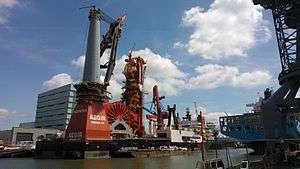
The J-lay system
In areas where the water is very deep, the S-lay system may not be appropriate because the pipeline leaves the stinger to go almost straight down. To avoid sharp bending at the end of it and to mitigate excessive sag bending, the tension in the pipeline would have to be high.[27] Doing so would interfere with the vessel's positioning, and the tensioner could damage the pipeline. A particularly long stinger could be used, but this is also objectionable since that structure would be adversely affected by winds and currents.[27] The J-lay system, one of the latest generations of lay-barge, is better suited for deep water environments. In this system, the pipeline leaves the vessel on a nearly vertical ramp (or tower). There is no overbend – only a sagbend of catenary nature (hence the J notation), such that the tension can be reduced. The pipeline is also less exposed to wave action as it enters the water.[28] However, unlike for the S-lay system, where pipe welding can be done simultaneously at several locations along the vessel deck's length, the J-lay system can only accommodate one welding station. Advanced methods of automatic welding are used to compensate for this drawback.[29]
The Reel-lay system
In the reel-lay system, the pipeline is assembled onshore and is spooled onto a large drum typically about 20 metres (66 ft) x 6 metres (20 ft) in size,[30] mounted on board a purpose-built vessel. The vessel then goes out to location to lay the pipeline. Onshore facilities to assemble the pipeline have inherent advantages: they are not affected by the weather or the sea state and are less expensive than seaborne operations.[20] Pipeline supply can be coordinated: while one line is being laid at sea, another one can be spooled onshore.[31] A single reel can have enough capacity for a full length flow line.[31] The reel-lay system, however, can only handle lower diameter pipelines – up to about 400 mm (16 in).[32] Also, the kind of steel making up the pipes must be able to undergo the required amount of plastic deformation as it is bent to proper curvature (by a spiral J-tube) when reeled around the drum, and straightened back (by a straightener) during the layout operations at the installation site.[33]
Stabilisation
Several methods are used to stabilise and protect submarine pipelines and their components. These may be used alone or in combinations.[34]
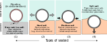
Trenching and burial

A submarine pipeline may be laid inside a trench as a means of safeguarding it against fishing gear (e.g. anchors) and trawling activity.[35][36] This may also be required in shore approaches to protect the pipeline against currents and wave action (as it crosses the surf zone). Trenching can be done prior to pipeline lay (pre-trenching), or afterward by seabed removal from below the pipeline (post-trenching). In the latter case, the trenching device rides on top of, or straddles, the pipeline.[35][36] Several systems are used to dig trenches in the seabed for submarine pipelines:
- Jetting: This is a post-trenching procedure whereby the soil is removed from beneath the pipeline by using powerful pumps to blow water on each side of it.[37][38]
- Mechanical cutting: This system uses chains or cutter disks to dig through and remove harder soils, including boulders,[39] from below the pipeline.
- Plowing: The plowing principle, which was initially used for pre-trenching, has evolved into sophisticated systems that are lighter in size for faster and safer operation.
- Dredging/excavation: In shallower water, the soil can be removed with a dredger or an excavator prior to laying the pipeline. This can be done in a number of ways, notably with a ′′cutter-suction′′ system, with the use of buckets or a with a backhoe.[35]
″A buried pipe is far better protected than a pipe in an open trench.″[40] This is commonly done either by covering the structure with rocks quarried from a nearby shoreline. Alternatively, the soil excavated from the seabed during trenching can be used as backfill. A significant drawback to burial is the difficulty in locating a leak should it arise, and for the ensuing repairing operations.[41]
Mattresses
Mattresses may be laid over the pipeline, or both under and over it depending on the substrate.[34]
- Frond mattresses have an effect similar to seaweed and tend to cause sand to accumulate. They must be anchored to the bottom to prevent being washed away.[34]
- Concrete mattresses are used to help hold part of the pipeline in place by their weight and reduce scour. They are usually heavy enough to be held in place by their own weight, as they are made from concrete blocks linked together by rope.[34]
- Combination mattresses of concrete mattress with overlaid frond mattress are also used.[34]
Ground anchors
Clamps holding the pipeline to piles may be used to prevent lateral movement.[34]
Saddle blocks
Precast concrete saddle blocks may be used to provide lateral support and hold the pipeline down more firmly.[34]
Sandbags and groutbags
These may be packed at the sides or under a pipeline to provide vertical and/or lateral support.[34]
Gravel dumps
Gravel may be dumped over parts of a pipeline to reduce scour and help stabilise against lateral movement.[34]
See also
References
- 1 2 3 4 5 6 Dean, p. 338-340
- 1 2 3 4 5 6 7 8 9 10 11 12 Gerwick, p. 583-585
- 1 2 3 Palmer & King, p. 2-3
- ↑ Bai & Bai, p. 22
- 1 2 3 Palmer & King, p. 11-13
- 1 2 Dean, p. 342-343
- 1 2 3 4 5 Palmer &King, p. 13–16
- 1 2 3 4 Dean, Sect. 7.2.2
- ↑ Palmer & Been, p. 182–187
- ↑ Croasdale et al. 2013
- ↑ Barrette 2011
- ↑ Palmer & King, p. 16-18
- 1 2 3 Ramakrishnan, p. 185
- ↑ Ramakrishnan, p. 186
- ↑ Dean, p.347-350
- ↑ Palmer & King, Chap.12
- 1 2 Bai & Bai, p. 910-912
- ↑ Wilson, Chap.1
- 1 2 3 Brown, p. 1
- 1 2 Palmer & King, p. 412
- ↑ Palmer & King, 12.4
- ↑ Palmer & King, p. 415
- ↑ Palmer & King, p. 417
- 1 2 3 4 Gerwick,15.2
- ↑ Palmer & King, p. 395
- ↑ Palmer & King, p. 397
- 1 2 Palmer & King, p. 401
- ↑ Palmer & King, p. 402
- ↑ Gerwick, p. 615
- ↑ Bai & Bai, p. 145
- 1 2 Gerwick, p. 611
- ↑ Bai & Bai, p. 144
- ↑ Gerwick, p. 610
- 1 2 3 4 5 6 7 8 9 Bevan, John, ed. (2005). "Section 1.7". The Professional Divers's Handbook (second ed.). 5 Nepean Close, Alverstoke, GOSPORT, Hampshire PO12 2BH: Submex Ltd. p. 34. ISBN 978-0950824260.
- 1 2 3 Palmer & King, sect. 12.5.1
- 1 2 Ramakrishnan, p. 212
- ↑ Palmer & King, p. 420
- ↑ Ramakrishnan, p. 214
- ↑ Palmer & King, p. 421
- ↑ Palmer & King, p. 424
- ↑ Palmer & King, p. 425
Bibliography
- Bai Y. & Bai Q. (2010) Subsea Engineering Handbook. Gulf Professional Publishing, New York, 919 p.
- Barrette, P (2011). "Offshore pipeline protection against seabed gouging by ice: An overview". Cold Regions Science and Technology. 69: 3–20. doi:10.1016/j.coldregions.2011.06.007.
- Brown R.J. (2006) Past, present, and future towing of pipelines and risers. In: Proceedings of the 38th Offshore Technology Conference (OTC). Houston, U.S.A.
- Croasdale K., Been K., Crocker G., Peek R. & Verlaan P. (2013) Stamukha loading cases for pipelines in the Caspian Sea. Proceedings of the 22nd International Conference on Port and Ocean Engineering under Arctic Conditions (POAC), Espoo, Finland.
- Dean E.T.R. (2010) Offshore Geotechnical Engineering - Principles and Practice, Thomas Telford, Reston, VA, U.S.A., 520 p.
- Gerwick B.C. (2007) Construction of marine and offshore structures. CRC Press, New York, 795 p.
- Palmer A.C. & Been K. (2011) Pipeline geohazards for Arctic conditions. In: W.O. McCarron (Editor), Deepwater Foundations and Pipeline Geomechanics, J. Ross Publishing, Fort Lauderdale, Florida, pp. 171–188.
- Palmer A. C. & King R. A. (2008). Subsea Pipeline Engineering (2nd ed.). Tulsa, USA: Pennwell, 624 p.
- Ramakrishnan T.V. (2008) Offshore engineering. Gene-Tech Books, New Delhi, 347 p.
- Wilson J.F. (2003) Structures in the offshore environment. In: J.F. Wilson (Editor), Dynamics of Offshore Structures. John Wiley & Sons, Hoboken, New Jersey, U.S.A., pp. 1–16.