Synchronous Ethernet
Synchronous Ethernet, also referred as SyncE, is an ITU-T standard for computer networking that facilitates the transference of clock signals over the Ethernet physical layer. This signal can then be made traceable to an external clock.
Overview
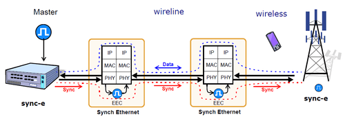
The aim of Synchronous Ethernet is to provide a synchronization signal to those network resources that may eventually require such a type of signal. The Synchronous Ethernet signal transmitted over the Ethernet physical layer should be traceable to an external clock, ideally a master and unique clock for the whole network. Applications include cellular networks, access technologies such as Ethernet passive optical network, and applications such as IPTV or VoIP.
Unlike time-division multiplexing networks, the Ethernet family of computer networks do not carry clock synchronization information. Several means are defined to address this issue. IETF’s Network Time Protocol, IEEE's 1588-2008 Precision Time Protocol are some of them.
SyncE was standardized by the ITU-T, in cooperation with IEEE, as three recommendations:
- ITU-T Rec. G.8261 that defines aspects about the architecture and the wander performance of SyncE networks
- ITU-T Rec. G.8262 that specifies Synchronous Ethernet clocks for SyncE
- ITU-T Rec. G.8264 that describes the specification of Ethernet Synchronization Messaging Channel (ESMC)
SyncE architecture minimally requires replacement of the internal clock of the Ethernet card by a phase locked loop in order to feed the Ethernet PHY.
Architecture

Extension of the synchronization network to consider Ethernet as a building block (ITU-T G.8261). This enables Synchronous Ethernet network equipment to be connected to the same synchronization network as Synchronous Digital Hierarchy (SDH). Synchronization for SDH can be transported over Ethernet and vice versa.
Clocks
ITU-T G.8262 defines Synchronous Ethernet clocks compatible with SDH clocks. Synchronous Ethernet clocks, based on ITU-T G.813 clocks, are defined in terms of accuracy, noise transfer, holdover performance, noise tolerance and noise generation. These clocks are referred as Ethernet Equipment Slave clocks. While the IEEE 802.3 standard specifies Ethernet clocks to be within ±100 ppm. EECs accuracy must be within ±4.6 ppm. In addition, by timing the Ethernet clock, it is possible to achieve Primary Reference Clock (PRC) traceability at the interfaces.
G.8262/Y.1362 is an ITU-T recommendation for Synchronous Ethernet that defines "timing characteristics of synchronous Ethernet equipment slave clock (EEC). "[1] It was first published in August 2007, amended in 2008 and 2010 and a new version published in 2010.[1]
Messaging channel
In SDH, the Synchronization Status Message (SSM) provides traceability of synchronization signals and it is therefore required to extend the SSM functionality to Synchronous Ethernet to achieve full interoperability with SDH equipment.
In SDH, the SSM message is carried in fixed locations within the SDH frame. However, in Ethernet there is no equivalent of a fixed frame. The mechanisms needed to transport the SSM over Synchronous Ethernet are defined by the ITU-T in G.8264 in cooperation with IEEE. More specifically, the ESMC, defined by the ITU-T is based on the Organization Specific Slow Protocol (OSSP), currently specified in IEEE 802.3ay. The ITU-T G.8264 defines a background or heart-beat message to provide a continuous indication of the clock quality level. However, event type messages with a new SSM quality level are generated immediately.
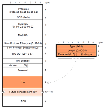
The ESMC protocol is composed of the standard Ethernet header for a slow protocol, an ITU-T specific header, a flag field and a type length value (TLV) structure. The SSM encoded within the TLV is a four-bit field whose meaning is described in ITU-T G.781.
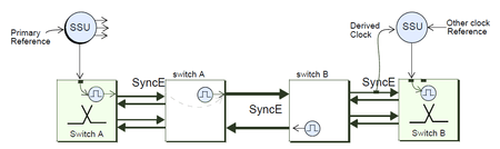
Synchronization architectures
A general requirement for SyncE was that any network element (NE) should have at least two reference clocks, and in addition, Ethernet interfaces must be able to generate their own synchronization signal in case they lose their external reference. If such is the case, it is said that the Ethernet node (EN) is in holdover. The synchronous signal must be filtered and regenerated by phase locked loop (PLL) at the Ethernet nodes since it degrades when passing through the network.
Network topologies
The synchronization and transport networks are partially mixed, since some NEs both transmit data and distribute clock signals to other NEs. The most common topologies are:
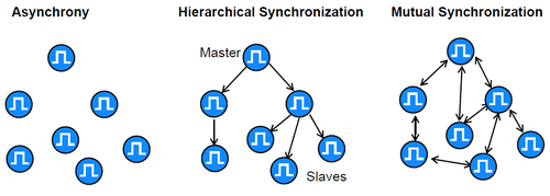
- Tree: This is a basic topology that relies on a master clock whose reference is distributed to the rest of the slave clocks. It has two weak points: it depends on only one clock, and the signals gradually degrade.
- Ring: Basically, this is a tree topology that uses ring configurations to propagate the synchronization signal. The ring topology offers a way to make a tree secure, but care must be taken to avoid the formation of synchronizing loops.
- Meshed: In this topology, nodes form interconnections between each other, in order to have redundancy in case of failure. However, synchronization loops occur easily and should be avoided.
SyncE networks do not usually have only one topology, but rather a combination of all of them. Duplication and security involving more than one master clock, and the existence of some kind of synchronization management protocol, are important features of modern networks. The aim is to minimize the problems associated with signal transport, and to avoid depending on only one clock in case of failure. As a result, we get an extremely precise, redundant, and solid synchronization network.
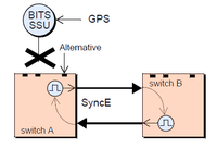
Interconnection of nodes
There are two basic ways to distribute synchronization:
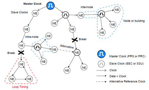
- Intranode, which is a high-quality slave clock known as either synchronization supply unit (SSU). These are responsible for distributing synchronization to NEs situated inside the node.
- Internode, where the synchronization signal is sent to another node by a link specifically dedicated to this purpose, or by a PHY signal.
Several type of networks can be used to transport the synchronous signal and could be combined indeed. Some of these networks are T1/E1, SONET/SDH and any rate, and SyncE. However legacy Ethernet is not suitable for transmitting synchronization signals. This is important because if the signal crosses a legacy Ethernet island then the synchronization is lost.
Synchronization signals
There are many signals suitable for transporting synchronization:
- Analog, of 1.544 and 2.048 MHz
- Digital, of 1.544 and 2.048 Mbit/s
- SyncE signal at any bit rate
- STM-n/OC-m line codes
Synchronization models
In SyncE, there are several ways to synchronize nodes:
- External timing: The EEC obtains its signal from an stand-alone synchronization equipment (SASE). This is a typical way to synchronize, and the NE usually also has an extra reference signal for emergency situations.
- Line timing: The NE obtains its clock by deriving it from one of the input signals.
- Through timing: Where the Tx outputs of one interface are synchronized with the Rx inputs of the opposite interface.
- Internal timing: In this mode, the internal clock of the EEC is used to synchronize outputs. It may be a temporary holdover stage after losing the synchronization signal, or it may be a simple line configuration where no other clock is available.
Timing loops
A timing loop is in bad synchronization when the clock signal has closed itself, but there is no clock, either master or slave, that would autonomously generate a non-deficient clock signal. This situation can be caused by a fault affecting an NE in such a way that it has been left without a reference clock, and therefore it has chosen an alternative synchronization: a signal that has turned out to be the same signal, returning by another route. A synchronization loop is a completely unstable situation that may provoke an immediate collapse of part of the network within the loop.
References
- 1 2 "G.8262 : Timing characteristics of a synchronous Ethernet equipment slave clock". International Telecommunication Union. July 2010.
External links
- SyncE explained under the installation and maintenance point of view
- Synchronous Network Architecture
- White Rabbit Synchronous Network, The White Rabbit Project