Transposition (telecommunications)
Transposition is the periodic swapping of positions of the conductors of a transmission line, in order to reduce crosstalk and otherwise improve transmission. In telecommunications this applies to balanced pairs whilst in power transmission lines three conductors are periodically transposed.
For cables, the swapping is gradual and continuous; that is the two or three conductors are twisted around each other. For communication cables this is called twisted pair. For overhead power lines or open pair communication lines, the conductors are exchanged at pylons, for example at transposition towers or at utility poles, respectively.
The mutual influence of electrical conductors is reduced by transposition. Transposition also equalizes their impedance relative to ground, thus avoiding one-sided loads in three-phase electric power systems. Transposing is an effective measure for the reduction of inductively linked normal mode interferences.
Power lines
For longer powerlines without branches, wires are transposed according to the transposing scheme. At closely branched grids and where several electric circuits share a route (in particular when the lines operate at different voltages) on the same pylons the outside unbalance of the line, which is caused by the other electric circuits, dominates. In these cases one finds large deviations from the transposing schemes. For example, in some such transpositions, only two of the three conductors on the pylons change their place. Also transpositions on pylons near power substations are used to get an optimal arrangement of the feeding system without crossing of conductors.
As the mutual influence of electric circuits can change after new lines are installed or old lines dismantled, certain transpositions may disappear or be added after new construction in electricity mains. In the case of a twisted line the individual conductors of an electric circuit swap places, either in their whole course (at cables) or at certain points (at overhead lines). The mutual influence of electrical conductors is reduced by transposing. The unbalance of the line, which can lead to one-sided loads in three-phase systems, is also reduced. Transposing of overhead lines is usually realized at so-called transposing pylons. Transposing is an effective measure for the reduction of inductively linked normal mode interferences.
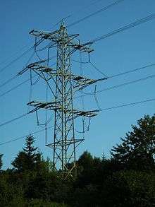
A transposing scheme is a pattern by which the conductors of overhead power lines are transposed at transposing structures. In order to ensure balanced capacitance of a three-phase line, each of the three conductors must hang once at each position of the overhead line.
At a transposition tower, the conductors change their relative places in the line. A transposing structure may be a standard structure with special cross arms, or may be a dead-end structure. The transposing is necessary as there is capacitance between conductors, as well as between conductors and ground. This is typically not symmetrical across phases. By transposing, the overall capacitance for the whole line is approximately balanced. Transposings also reduce effects to communiciations circuits.[1]
Telecommunication
In communications cables, transposition is used to reduce coupling between circuits in the same cable. The principal measure is the pitch or lay length,[2] the distance over which the pairs of a circuit are twisted. By twisting, the wires become longer than the cable. The stranding factor indicates the relationship of single wire length to cable length; it amounts to with communication cables about 1.02 to 1.04.
Kinds of stranding
In practice the following kinds of stranding occur more frequently:
- Pair stranding: Two single wires are stranded to twisted pair transmission line.
- Three-stranding: Three single wires are stranded to a tripartite group.
- Four-stranding: Two tightly twisted pairs may be loosely twisted together, or:
- Star quad twisting: Four single wires maintain the same relation to each other in the quad, whereby the members of a twisted pair face each other diagonally.
Transmission technique
The kinds of stranding have different transmission characteristics. The capacity of a stranding affects itself, for example the two conductors of a quadruple run parallel over the entire cable length in star quad twisting. Capacitance between the conductors is thus substantially higher than with Dieselhorst Martin (DHM) - stranding in which the situation of the conductors to each other in the cable changes repeatedly. Because of the smaller work capacity of the DHM stranding it is possible to form additional electric circuits with the help of a phantom circuit. Since the phantom transducers are turned on to in the middle of the master transducers, the currents of the phantom circuit on the two coming Rome circles compensate themselves.
See also
References
- ↑ Central Station Engineers, Electrical Transmission and Distribution Reference Book, Westinghouse Electric Corporation, East Pittsburgh, Pennsylvania, 4th Ed. 1950 pages 748, 778
- ↑ Lay Length cablecad.com