Ultrasonic testing

Step 1: The UT probe is placed on the root of the blades to be inspected with the help of a special borescope tool (video probe).
Step 2: Instrument settings are input.
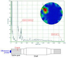
Step 3: The probe is scanned over the blade root. In this case, an indication (peak in the data) through the red line (or gate) indicates a good blade; an indication to the left of that range indicates a crack.
Ultrasonic testing (UT) is a family of non-destructive testing techniques based on the propagation of ultrasonic waves in the object or material tested. In most common UT applications, very short ultrasonic pulse-waves with center frequencies ranging from 0.1-15 MHz, and occasionally up to 50 MHz, are transmitted into materials to detect internal flaws or to characterize materials. A common example is ultrasonic thickness measurement, which tests the thickness of the test object, for example, to monitor pipework corrosion.
Ultrasonic testing is often performed on steel and other metals and alloys, though it can also be used on concrete, wood and composites, albeit with less resolution. It is used in many industries including steel and aluminium construction, metallurgy, manufacturing, aerospace, automotive and other transportation sectors.
History
On May 27, 1940, U.S. researcher Dr. Floyd Firestone of the University of Michigan applies for a U.S. invention patent for the first practical ultrasonic testing method. The patent is granted on April 21, 1942 as U.S. Patent No. 2,280,226, titled "Flaw Detecting Device and Measuring Instrument". Extracts from the first two paragraphs of the patent for this entirely new nondestructive testing method succinctly describe the basics of such ultrasonic testing. "My invention pertains to a device for detecting the presence of inhomogeneities of density or elasticity in materials. For instance if a casting has a hole or a crack within it, my device allows the presence of the flaw to be detected and its position located, even though the flaw lies entirely within the casting and no portion of it extends out to the surface. ... The general principle of my device consists of sending high frequency vibrations into the part to be inspected, and the determination of the time intervals of arrival of the direct and reflected vibrations at one or more stations on the surface of the part."
James F. McNulty (U.S. radio engineer) of Automation Industries, Inc., then, in El Segundo, California, an early improver of the many foibles and limits of this and other nondestructive testing methods, teaches in further detail on ultrasonic testing in his U.S. Patent 3,260,105 (application filed December 21, 1962, granted July 12, 1966, titled “Ultrasonic Testing Apparatus and Method”) that “Basically ultrasonic testing is performed by applying to a piezoelectric crystal transducer periodic electrical pulses of ultrasonic frequency. The crystal vibrates at the ultrasonic frequency and is mechanically coupled to the surface of the specimen to be tested. This coupling may be effected by immersion of both the transducer and the specimen in a body of liquid or by actual contact through a thin film of liquid such as oil. The ultrasonic vibrations pass through the specimen and are reflected by any discontinuities which may be encountered. The echo pulses that are reflected are received by the same or by a different transducer and are converted into electrical signals which indicate the presence of the defect.”
How it works

In ultrasonic testing, an ultrasound transducer connected to a diagnostic machine is passed over the object being inspected. The transducer is typically separated from the test object by a couplant (such as oil) or by water, as in immersion testing. However, when ultrasonic testing is conducted with an Electromagnetic Acoustic Transducer (EMAT) the use of couplant is not required.
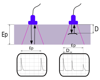
There are two methods of receiving the ultrasound waveform: reflection and attenuation. In reflection (or pulse-echo) mode, the transducer performs both the sending and the receiving of the pulsed waves as the "sound" is reflected back to the device. Reflected ultrasound comes from an interface, such as the back wall of the object or from an imperfection within the object. The diagnostic machine displays these results in the form of a signal with an amplitude representing the intensity of the reflection and the distance, representing the arrival time of the reflection. In attenuation (or through-transmission) mode, a transmitter sends ultrasound through one surface, and a separate receiver detects the amount that has reached it on another surface after traveling through the medium. Imperfections or other conditions in the space between the transmitter and receiver reduce the amount of sound transmitted, thus revealing their presence. Using the couplant increases the efficiency of the process by reducing the losses in the ultrasonic wave energy due to separation between the surfaces.
Features
Advantages
- High penetrating power, which allows the detection of flaws deep in the part.
- High sensitivity, permitting the detection of extremely small flaws.
- In many cases only one surface needs to be accessible.
- Greater accuracy than other nondestructive methods in determining the depth of internal flaws and the thickness of parts with parallel surfaces.
- Some capability of estimating the size, orientation, shape and nature of defects.
- Some capability of estimating the structure of alloys of components with different acoustic properties
- Non hazardous to operations or to nearby personnel and has no effect on equipment and materials in the vicinity.
- Capable of portable or highly automated operation.
- Results are immediate. Hence on the spot decisions can be made.
Disadvantages
- Manual operation requires careful attention by experienced technicians. The transducers alert to both normal structure of some materials, tolerable anomalies of other specimens (both termed “noise”) and to faults therein severe enough to compromise specimen integrity. These signals must be distinguished by a skilled technician, possibly requiring follow up with other nondestructive testing methods.[1]
- Extensive technical knowledge is required for the development of inspection procedures.
- Parts that are rough, irregular in shape, very small or thin, or not homogeneous are difficult to inspect.
- Surface must be prepared by cleaning and removing loose scale, paint, etc., although paint that is properly bonded to a surface need not be removed.
- Couplants are needed to provide effective transfer of ultrasonic wave energy between transducers and parts being inspected unless a non-contact technique is used. Non-contact techniques include Laser and Electro Magnetic Acoustic Transducers (EMAT).
- Inspected items must be water resistant, when using water based couplants that do not contain rust inhibitors.
Standards
- ISO 2400: Non-destructive testing - Ultrasonic testing - Specification for calibration block No. 1 (2012)
- ISO 7963: Non-destructive testing — Ultrasonic testing — Specification for calibration block No. 2 (2006)
- ISO 10863: Non-destructive testing of welds -- Ultrasonic testing -- Use of time-of-flight diffraction technique (TOFD) (2011)
- ISO 11666: Non-destructive testing of welds — Ultrasonic testing — Acceptance levels (2010)
- ISO 16809: Non-destructive testing -- Ultrasonic thickness measurement (2012)
- ISO 16831: Non-destructive testing -- Ultrasonic testing -- Characterization and verification of ultrasonic thickness measuring equipment (2012)
- ISO 17640: Non-destructive testing of welds - Ultrasonic testing - Techniques, testing levels, and assessment (2010)
- ISO 22825, Non-destructive testing of welds - Ultrasonic testing - Testing of welds in austenitic steels and nickel-based alloys (2012)
- ISO 5577: Non-destructive testing -- Ultrasonic inspection -- Vocabulary (2000)
- EN 583, Non-destructive testing - Ultrasonic examination
- EN 1330-4, Non destructive testing - Terminology - Part 4: Terms used in ultrasonic testing
- EN 12668-1, Non-destructive testing - Characterization and verification of ultrasonic examination equipment - Part 1: Instruments
- EN 12668-2, Non-destructive testing - Characterization and verification of ultrasonic examination equipment - Part 2: Probes
- EN 12668-3, Non-destructive testing - Characterization and verification of ultrasonic examination equipment - Part 3: Combined equipment
- EN 12680, Founding - Ultrasonic examination
- EN 14127, Non-destructive testing - Ultrasonic thickness measurement
(Note: Part of CEN standards in Germany accepted as DIN EN, in Czech Republic as CSN EN.)
See also
- Non-Contact Ultrasound
- Phased array ultrasonics
- Time-of-flight diffraction ultrasonics (TOFD)
- Time-of-flight ultrasonic determination of 3D elastic constants (TOF)
- Internal rotary inspection system (IRIS) ultrasonics for tubes
- EMAT Electromagnetic Acoustic Transducer
- ART (Acoustic Resonance Technology)
References
- ↑ U.S. Patent 3,260,105 for Ultrasonic Testing Apparatus and Method to James F. McNulty at lines 37-48 and 60-72 of Column 1 and lines 1-4 of Column 2.
Further reading
| Wikimedia Commons has media related to Ultrasonic flaw detection. |
- Albert S. Birks, Robert E. Green, Jr., technical editors ; Paul McIntire, editor. Ultrasonic testing, 2nd ed. Columbus, OH : American Society for Nondestructive Testing, 1991. ISBN 0-931403-04-9.
- Josef Krautkrämer, Herbert Krautkrämer. Ultrasonic testing of materials, 4th fully rev. ed. Berlin; New York: Springer-Verlag, 1990. ISBN 3-540-51231-4.
- J.C. Drury. Ultrasonic Flaw Detection for Technicians, 3rd ed., UK: Silverwing Ltd. 2004. (See Chapter 1 online (PDF, 61 kB)).
- Nondestructive Testing Handbook, Third ed.: Volume 7, Ultrasonic Testing. Columbus, OH: American Society for Nondestructive Testing.
- Detection and location of defects in electronic devices by means of scanning ultrasonic microscopy and the wavelet transform measurement, Volume 31, Issue 2, March 2002, Pages 77–91, L. Angrisani, L. Bechou, D. Dallet, P. Daponte, Y. Ousten
- Charles Hellier (2003). "Chapter 7 - Ultrasonic Testing". Handbook of Nondestructive Evaluation. McGraw-Hill. ISBN 0-07-028121-1.
External links
- Ultrasonic testing
- Film about Russian ultrasonic testing unit ASK-132 in Kalinin NPP
- Ultrasonic Testing on NDTWiki.com
- Video on ultrasonic testing, Karlsruhe University of Applied Sciences