Cyclorotor

A cyclorotor, cycloidal rotor, cycloidal propeller or cyclogiro, is a fluid propulsion device that converts shaft power into the acceleration of a fluid using a rotating axis perpendicular to the direction of fluid motion. It uses several blades with a spanwise axis parallel to the axis of rotation and perpendicular to the direction of fluid motion. These blades are cyclically pitched twice per revolution to produce force (thrust or lift) in any direction normal to the axis of rotation. Cyclorotors are used for propulsion, lift, and control on air and water vehicles. An aircraft using cyclorotors as the primary source of lift, propulsion, and control is known as a cyclogyro. The patented application,[1][2][3] used on the ships with particular actuation mechanisms both mechanics or hydraulics is named from the name of the German company that produces them: Voith–Schneider cycloidal propellers.
Operating Principle

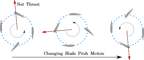
Cyclorotors produce thrust by combined action of a rotation of a fixed point of the blades around a centre and the osillation of the blades that changes over time their angle-of-attack. The joint action of the advancement produced by the orbital motion and pitch angle variation generates a higher thrust even at low speed with respect of any other propeller. In hover, the blades are actuated to a positive pitch (outward from the center of the rotor) on the upper half of their revolution and a negative pitch (inward towards the axis of rotation) over the lower half inducing a net upward aerodynamic force and opposite fluid downwash. By varying the phase of this pitch motion the force can be shifted sidewise or downward. Before blade stall, increasing the amplitude of the pitching kinematics will magnify thrust.
History
The origin of the rotocycloid propeller are Russian and relates to aeronautic domain.[4] Sverchkov's Samoljot, St-Peterburg, 1909, or "wheel orthopter" has been the first vehicle expressly thought for using this propulsion. Its scheme came near to cyclogiro, but it's difficult to classify it precisely. It had three flat surfaces and a rudder; rear edge of one of surfaces could be bent, replacing the action of an elevator. Lift and thrust had to be created by paddle wheels consisting of 12 blades, established in pairs under a 120° angle. The blades of a concave shape were changing an angle of incidence by the means of eccentrics and springs. In a bottom of the craft 10 hp engine was arranged. Transmission was ensured by a belt. Empty weight was about 200 kg. "Samoljot" was constructed by the military engineer E.P.Sverchkov with the grants of the Main Engineering Agency in St.Petersburg in 1909, was demonstrated at the Newest Inventions Exhibition and won a medal. Otherwise, it could not pass the preliminary tests without flying. In 1914, Russian inventor and scientist A.N. Lodygin has addressed to Russian government with the project of the cyclogiro-like aircraft, which scheme wabs similar to Sverchkov's "Samoljot". The project was not carried out. In 1933, experiments in Germany by Adolf Rohrbach resulted in a paddle-wheel wing arrangement.[5] Oscillating winglets went from positive to negative angles of attack during each revolution to create lift, and their eccentric mounting would, in theory, produce nearly any combination of horizontal and vertical forces. The DVL evaluated Rohrbach’s design, but the foreign aviation journals of the time cast doubt on the soundness of the design which meant that funding for the project could not be raised, even with a latter proposal as a Luftwaffe transport aircraft. There appears to be no evidence that this design was ever built, let alone flown. Based on Rohrbach’s paddle-wheel research, however, Platt in the US designed by 1933 his own independent Cyclogyro. His paddle-wheel wing arrangement was awarded a US patent (which was only one of many similar patents on file), and underwent extensive wind-tunnel testing at MIT in 1927. Despite this, there is no evidence Platt’s aircraft was ever built. The first operative cycloid propulsion has been developed at Voight. Its origins date to the decision of the Voith company to focus on the business of transmission gear assemblies for turbines. The famous Voight propeller has , based on its fluid-dynamics know-how gained from previous turbine projects. It was invented by Ernst Schneider, and enhanced by Voith. It was launched with name of Voith-Schneider Propeller (VSP) for commercial vessels. This new marine drive could significantly improve the manoeuvrability of a ship as demonstrated in the successful sea trials on the test boat Torqueo, in 1937. The first Voith Schneider Propellers were put into operation in the narrow canals of Venice, Italy. During the 1937 World Fair in Paris, Voith was awarded the grand prize – three times – for its exhibition of Voith Schneider Propellers and Voith turbo-transmissions. A year later, two of Paris' fire-fighting boats started operating with the new VSP system.
Design advantages and challenges
Rapid thrust vectoring
Cyclorotors provide a high degree of control. Traditional propellers, rotors, and jet engines produce thrust only along their axis of rotation and require rotation of the entire device to alter the thrust direction. This rotation requires large forces and comparatively long time scales since the propeller inertia is considerable, and the rotor gyroscopic forces resist rotation. For many practical applications (helicopters, airplanes, ships) this requires rotating the entire vessel. In contrast, cyclorotors need only to vary the blade pitch motions. Since there is little inertia associated with blade pitch change, thrust vectoring in the plane perpendicular to the axis of rotation is rapid.[6]
High advance ratio thrust and symmetric lift
Cyclorotors can produce lift and thrust at high advance ratios, which, in theory, would enable a cyclogyro aircraft to fly at subsonic speeds well exceeding those of single rotor helicopters. Single rotor helicopters are limited in forward speed by a combination of retreating blade stall and sonic blade tip constraints.[7] As helicopters accelerate, the tip of the advancing blade experiences a wind velocity that is the sum of the helicopter forward speed and rotor rotational speed. This value cannot exceed the speed of sound if the rotor is to be efficient and quiet. Slowing the rotor rotational speed avoids this problem, but presents another disadvantage. If the problem is assumed according to the traditional method of the composition of velocity it easy to understand that the velocity experienced by the retreating blade assumes a value that is produced by the vector composition of two velocities: the velocity of blade rotation and the freestream velocity. In this conditions, it is evident that in presence of a sufficiently high advance ratio the velcity of air on the retreating blade is low. The flapping movement of the blade changes the angle of attach. It is then possible for the blade to reach the stall condition.[8] In this case it is necessary that the stalling blade increases the pitch angle to keep some lift capability. This negative element oblige to focus a particular attention on the accurate design of the system in order to avoid this risk. It is then necessary an accurate choice of the wing profile, a careful dimensioning process of the radius of the rotor for the specific speed range.[9] Slow speed Cyclorotos bypass this problem via a horizontal axis of rotation and operating at comparatively low blade tip speed. For higher speeds which could be necessary for future industrial applications it seems necessary to adopt more sophisticated strategies and solutions. A solution is the independent actuation of the blades which have been recently patented and successfully tested for naval use [10] by use on hydraulic actuation system. In the aeronautic domain similar solutions appear difficult, because of the necessity of maintaining a low ratio between weight and thrust.[11] One solution has been proposed by the Austrian inventor Meinhard Schwaiger with his turbomachine patent.[12] The horizontal axis of rotation always provides an advancement of the upper blades, that produce always a positive lift by the full rotor.[13] These characteristics could help overcome two issues met on helicopters: the low energy efficiency and the advance ratio limitation.[14][15][16]
Unsteady aerodynamics
The advancement of the blades and oscillations are the two dynamic actions which are produced by a cyclorotor. It is evident that the wing-blades of a cyclorotor operates in different way than a traditional aircraft wing or a traditional helicopter wing. The blades of a cyclorotor oscillates by rotation around an a point that rotating describes an ideal circumference. The combination of the advancement motion of the centre of rotation of the blade and the oscillation of the blade (it is a movement somehow similar to the pendulum), which continue to vary its pitch generate a complex set of aerodynamic phenomena:
- the delay of the blade stall;
- an increase of the maximum blade lift coefficient at low Reynolds numbers.
The two effects are evidently correlated with a general increase of the thrust produced. If compared to an helicopter or any other propeller, it is evident that the same blade section in a rotocycloid produces much more thrust at the same Reynolds number. This effect can be explained by considering the traditional behavior of a propeller. At low Reynolds numbers turbulence and laminar flow conditions can ever been reached. Considering a traditional wing profile it is evident that those conditions minimizes the speed differences between upper and lower face of the wing. It is then evident that both lift and stall speed are reduced. A consequence is a reduction of angle of attach at which stall conditions are reached. In this regime, conventional propellers and rotors must use larger blade area and rotate faster to achieve the same propulsive forces and lose more energy to blade drag. It is then evident that a cyclorotor is much more energy efficient than any other propeller. Actual cyclorotors bypass this problem by quickly increasing and then decreasing blade angle of attack, which temporarily delays stall and achieves a high lift coefficient. This unsteady lift makes cyclorotors more efficient at small scales, low velocities, and high altitudes than traditional propellers. It is otherwise evident that many living beings are still much more efficient, because they can change non only the pitch but also the shape of their wings, such as birds [17][18] and some insects or they can change the property of the boundary layer such as sharkskin.[19] Some research tries to acquire the same level of efficiency of the natural examples of wings or surfaces.[20] One direction is to introduce morphing wing concepts,.[21][22] Another relates to the introduction of boundary layer control mechanisms, such as dielecric barrier discharge,.[23][24]
Noise
During experimental evaluation, cyclorotors produced little aerodynamic noise. This likely due to the lower blade tip speeds, which produce lower intensity turbulence following the blades.[25]
Hovering thrust efficiency
In small-scale tests, cyclorotors achieved a higher power loading than comparable scale traditional rotors at the same disk loading. This is attributed to utilizing unsteady lift and consistent blade aerodynamic conditions. The rotational component of velocity on propellers increases from root to tip and requires blade chord, twist, airfoil, etc., to be varied along the blade. Since the cyclorotor blade span is parallel to the axis of rotation, each spanwise blade section operates at similar velocities and the entire blade can be optimized.[26][27]
Structural considerations
Cyclorotor blades require support structure for their positioning parallel to the rotor axis of rotation. This structure, sometimes referred to as "spokes," adds to the parasite drag and weight of the rotor.[28] Cyclorotor blades are also centrifugally loaded in bending (as opposed to the axial loading on propellers), which requires blades with an extremely high strength to weight ratio or intermediate blade support spokes. Early 20th century cyclorotors featured short blade spans, or additional support structure to circumvent this problem.[29][30][31]
Blade pitch considerations
Cyclorotors require continuously actuated blade pitch. The relative flow angle experienced by the blades as they rotate about the rotor varies substantially with advance ratio and rotor thrust. To operate most efficiently a blade pitch mechanism should adjust for these diverse flow angles. High rotational velocities makes it difficult to implement an actuator based mechanism, and it is challenging to design and construct a mechanical based device. While the pitching motions used in hover are not optimized for forward flight, in experimental evaluation they were found to provide efficient flight up to an advance ratio near one.[28][32][33][34]
Applications
Ship propulsion and control
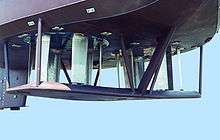
The most widespread application of cyclorotors is for ship propulsion and control. In ships the cyclorotor is mounted with the axis of rotation vertical so that thrust can quickly be vectored any direction in plane with the water surface. In 1922, Kurt Kirstin fitted a pair of cyclorotors to a 32 ft boat in Washington, which eliminated the need for a rudder and provided extreme maneuverability. While the idea floundered in the United States after the Kirsten-Boeing Propeller Company lost a US Navy research grant, the Voith-Schneider propeller company successfully commercially employed the propeller. This Voith-Schneider propeller was fitted to more than 100 ships prior to the outbreak of the second world war.[35] Today, the same company sells the same propeller for highly maneuverable watercraft. It is applied on offshore drilling ships, tugboats, and ferries.[36]
Airship propulsion and control
A large exposed area makes airships susceptible to gusts and difficult to takeoff, land, or moor in windy conditions. Propelling airships with cyclorotors could enable flight in more severe atmospheric conditions by compensating for gusts with rapid thrust vectoring. Following this idea, the US Navy seriously considered fitting of 6 primitive Kirsten-Boeing cyclorotors to the USS Shenandoah airship. The Shenandoah crashed while transiting a squall line on 3 September 1925 before any possible installation and testing.[37] No large scale tests have been attempted since, but a 20m cyclorotor airship demonstrated improved performance over a traditional airship configuration in a test.[38]
Micro Air Vehicles (MAVs)
The performance of traditional rotors is severely deteriorated at low Reynolds Numbers by low angle-of-attack blade stall. Current hover-capable MAVs can stay aloft for only minutes.[27] Cyclorotor MAVs (very small scale cyclogyros) could utilize unsteady lift to extend endurance. The smallest cyclogyro flown to date weighs only 29 grams and was developed by the advanced vertical flight laboratory at Texas A&M university.[39]
Cyclogyros
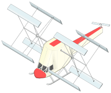
A cyclogyro is a vertical takeoff and landing aircraft implementing cyclorotors as the principal source of lift, propulsion, and control. Advances in cyclorotor aerodynamics made the first untethered model cyclogyro flight possible in 2012. Since then, universities and companies have successfully flown small-scale cyclogyros in several configurations.[28][40]
Wind Turbines
Wind turbines are a potential application of cyclorotors.[41] They are named in this case variable-pitch vertical axis wind turbines, with large benefits with respect to traditional VAWTs.[42] This kind of turbines is stated to overcome most of the traditional limitations of traditional Darrieus VAWTs.[43] Their behavior and modeling is opposite to the one of propellers.[44]
See also
References
- ↑ https://www.google.com/patents/US3241618?dq=voith+schneider&hl=it&sa=X&ved=0ahUKEwiz-pDS4qXPAhViDMAKHWw7AkIQ6AEINzAD
- ↑ https://www.google.com/patents/US4752258?dq=voith+schneider&hl=it&sa=X&ved=0ahUKEwiz-pDS4qXPAhViDMAKHWw7AkIQ6AEIUjAG
- ↑ https://www.google.com/patents/DE3214015A1?cl=en&dq=voith+schneider&hl=it&sa=X&ved=0ahUKEwiz-pDS4qXPAhViDMAKHWw7AkIQ6AEIJTAB
- ↑ http://www.rotoplan.narod.ru/history_e.htm
- ↑ http://discaircraft.greyfalcon.us/Rohrbach%20Cyclogyro.htm
- ↑ Jarugumilli, T; Benedict, M; Chopra, I (2011). "Experimental Optimization and Performance Analysis of a MAV Scale Cycloidal Rotor". 49th AIAA Aerospace Sciences Meeting including the New Horzons Forum and Aerospace Exposition.
- ↑ Leishman, J. Gordon (2007). The helicopter : thinking forward, looking back. College Park, Md.: College Park Press. ISBN 978-0-9669553-1-6.
- ↑ Benedict, M., Mattaboni, M., Chopra, I., & Masarati, P. (2011). Aeroelastic analysis of a micro-air-vehicle-scale cycloidal rotor in hover. AIAA journal, 49(11), 2430-2443. http://www.enu.kz/repository/2010/AIAA-2010-2888.pdf
- ↑ Benedict, M., Jarugumilli, T., & Chopra, I. (2013). Effect of rotor geometry and blade kinematics on cycloidal rotor hover performance. Journal of Aircraft, 50(5), 1340-1352.
- ↑ https://www.google.com/patents/EP0785129B1
- ↑ Páscoa, J. C., Dumas, A., & Trancossi, M. (2012, November). A Novel Look at the Performance of the Cyclorotor Propulsion System for Air Vehicles. In ASME 2012 International Mechanical Engineering Congress and Exposition (pp. 455-462). American Society of Mechanical Engineers.
- ↑ https://www.google.com/patents/EP2798205B1
- ↑ Eastman, F (1945). "The Full-Feathering Cyclogiro". University of Washington Technical Report.
- ↑ Mayo, D. B., & Leishman, J. G. (2010). Comparison of the hovering efficiency of rotating wing and flapping wing micro air vehicles. Journal of the American Helicopter Society, 55(2), 25001-25001.
- ↑ Benedict, M., Ramasamy, M., & Chopra, I. (2010). Improving the aerodynamic performance of micro-air-vehicle-scale cycloidal rotor: an experimental approach. Journal of aircraft, 47(4), 1117-1125. http://citeseerx.ist.psu.edu/viewdoc/download?doi=10.1.1.174.722&rep=rep1&type=pdf
- ↑ Leger Monteiro, Jakson Augusto, et al. "Aerodynamic optimization of cyclorotors." Aircraft Engineering and Aerospace Technology: An International Journal 88.2 (2016): 232-245. bbbbbb
- ↑ Marchetti, K., Price, T., & Richman, A. (1995). Correlates of wing morphology with foraging behaviour and migration distance in the genus Phylloscopus. Journal of Avian Biology, 177-181.b
- ↑ Mönkkönen, M. (1995). Do migrant birds have more pointed wings?: a comparative study. Evolutionary Ecology, 9(5), 520-528.
- ↑ Oeffner, J., & Lauder, G. V. (2012). The hydrodynamic function of shark skin and two biomimetic applications. Journal of Experimental Biology, 215(5), 785-795. http://jeb.biologists.org/content/215/5/785.full
- ↑ Liebe, R. (Ed.). (2006). Flow Phenomena in Nature: Inspiration, learning and application (Vol. 2). Wit Press.
- ↑ Roccia, B., Preidikman, S., Gómez, C., & Ceballos, L. AEROELASTICIDAD DE SISTEMAS AERONÁUTICOS INMERSOS EN FLUJOS SUBSÓNICOS–UNA NUEVA METODOLOGÍA. http://aero.ing.unlp.edu.ar/caia/Actas-CAIA3/14.pdf
- ↑ Faria, C. T. D. (2010). Controle da variação do arqueamento de um aerofólio utilizando atuadores de memória de forma. http://repositorio.unesp.br/bitstream/handle/11449/94509/faria_ct_me_ilha.pdf?sequence=1&isAllowed=y
- ↑ Xisto, C. M., Páscoa, J. C., Abdollahzadeh, M., Leger, J. A., Schwaiger, M., Wills, D., ... & Gagon, L. (2014, July). Pecyt-plasma enhaced cycloidal thruster. In 50th AIAA/ASME/SAE/ASEE Joint Propulsion Conference (p. 3854).
- ↑ Xisto, C. M., Páscoa, J. C., Abdollahzadeh, M., Leger, J. A., Schwaiger, M., Wills, D., ... & Gagon, L. (2014, July). Pecyt-plasma enhaced cycloidal thruster. In 50th AIAA/ASME/SAE/ASEE Joint Propulsion Conference (p. 3854). https://www.researchgate.net/profile/Carlos_Xisto/publication/264310504_PECyT_-_Plasma_enhanced_cycloidal_thruster/links/53d8086a0cf2631430bff90c.pdf
- ↑ Boschma, J.; McNabb, M. (1998). "Cycloidal Propulsion for UAV VTOL Applications". Naval Air Warfare Center-Aircraft Division.
- ↑ Jarugumilli, T.; Benedict, M.; Chopra, I. (4 January 2011). "Experimental Optimization and Performance Analysis of a MAV Scale Cycloidal Rotor". AIAA Aerospace Sciences Meeting.
- 1 2 Benedict, Moble (2010). "Fundamental Understanding of the Cycloidal-Rotor Concept for Micro Air Vehicle Applications". PhD Dissertation, University of Maryland.
- 1 2 3 Adams, Z.; Benedict, M.; Hrishikeshavan, V.; Chopra, I. (2013). "Design, Development, and Flight Test of a Small-Scale Cyclogyro UAV Utilizing a Novel Cam-Based Passive Blade Pitching Mechanism". International Journal of Micro Air Vehicles.
- ↑ Wheatley, J. (1935). "Wind-Tunnel Tests of a Cyclogiro Rotor". National Advisory Committee for Aeronautics.
- ↑ Strandgren, C. (1933). "The Theory of the Strandgren Cyclogyiro". National Advisory Committee for Aeronautics.
- ↑ Hwang, I.; Min, S.; Jeong, I.; Lee, Y.; Kim, S. (2006). "Efficiency Improvements of a New Vertical Axis Wind Turbine by Individual Active Control of Blade Motion". Smart Structures and Materials 2006: Smart Structures and Integrated Systems.
- ↑ Clark, R (24 July 2006). "VTOL to Transonic Aircraft". SBIR A02.07 Final Technical Report.
- ↑ Benedict, M.; Jarugumilli, T.; Lakshminarayan, V.; Chopra, I. (2012). "Experimental and Computational Studies to Understand the Role of Flow Curvature Effects on the Aerodynamic Performance of a MAV-Scale Cycloidal Rotor in Forward Flight". American Institute of Aeronautics and Astronautics.
- ↑ Jarugumilli, T. (2012). "Experimental Invertigation of the Forward Flight Performance of a MAV-Scale Cycloidal Rotor". American Helicopter Society.
- ↑ Levinson, M. (1991). "Illegal Immigrant Extraordinary: The Aeronautical Years, 1920-1938". Journal of the West.
- ↑ "Voith Schneider Propeller". Voith.
- ↑ Sachse, H (1926). "Kirsten-Boeing Propeller". Technical Report, National Advisory Committee for Aeronautics Translation from Zeitschrift fur Flugtechnik und Motorluftschiffahrt.
- ↑ Nozaki, M.; Sekiguchi, Y.; Matsuuchi, K.; Onda, M.; Murakami, Y.; Sano, M.; Akinaga, W.; Fujita, K. (4 May 2009). "Research and Development on Cycloidal Propellers for Airships". 18th AIAA Lighter-Than-Air Systems Technology Conference.
- ↑ Runco, C.; Coleman, D.; Benedict, M. (4 January 2016). "Design and Development of a Meso-Scale Cyclocopter". AIAA SciTech.
- ↑ Benedict, M.; Shrestha, E.; Hrishikeshavan, V.; Chopra, I. (18 January 2012). "Development of a 200 gram Twin-Rotor Micro Cyclocopter Capable of Autonomous Hover". American Helicopter Society Future Vertical Lift Aircraft Design Conference, San Francisco, CA.
- ↑ Lazauskas, L. (1992). Three pitch control systems for vertical axis wind turbines compared. Wind engineering, 16(5), 269-282.
- ↑ Pawsey, N. C. K. (2002). Development and evaluation of passive variable-pitch vertical axis wind turbines. Australia: University of New South Wales. http://citeseerx.ist.psu.edu/viewdoc/download?doi=10.1.1.470.4573&rep=rep1&type=pdf
- ↑ Kirke, B. K., & Lazauskas, L. (2011). Limitations of fixed pitch Darrieus hydrokinetic turbines and the challenge of variable pitch. Renewable Energy, 36(3), 893-897.
- ↑ Xisto, C. M., Páscoa, J. C., & Trancossi, M. (2016). Geometrical Parameters Influencing the Aerodynamic Efficiency of a Small-Scale Self-Pitch High-Solidity VAWT. Journal of Solar Energy Engineering, 138(3), 031006. https://www.researchgate.net/profile/Jose_Pascoa/publication/291355127_Geometrical_Parameters_Influencing_the_Aerodynamic_Efficiency_of_a_Small-Scale_Self-Pitch_High_Solidity_VAWT/links/56e062b308ae979addf0f15d.pdf