AN/APQ-7
The AN/APQ-7, or Eagle, was a radar bombsight system developed by the US Army Air Force. Early studies started in late 1941 under the direction of Luis Alvarez at the MIT Radiation Laboratory, but full-scale development did not begin until April 1943. By this time US-built, higher frequency systems promising better performance over the existing British H2S radar were entering production. Eagle's even higher resolution was considered important to Air Force planners who preferred precision bombing but were failing to deliver it, and high hopes were put on the system's abilities to directly attack small targets like docks and bridges.
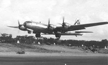
The war effort was already winding down when the first production units arrived in late 1944. A small number were fitted to B-17 Flying Fortress and B-24 Liberator aircraft intended for use in Europe, but none of these arrived in time to see action before the war ended. The system was first used operationally with the B-29 Superfortress in the Pacific Theater starting in May 1945. The addition of the APA-46 and 47 "Nosmo" synchronized a Norden bombsight with the APQ-7, and the entire assembly became known as the APQ-7A. The war ended shortly after this system was introduced, and Eagle saw little real world use. Post-war efforts focused on the K-system, as Eagle's unique antenna design made it difficult to use with higher speed jet powered bombers.
History
Impetus
Late in 1940, as part of the Tizard Mission, Taffy Bowen had introduced US scientists to the British work on microwave radar using the cavity magnetron. After returning to the UK, Bowen's earlier observation about differences in ground returns noticed in early experiments led Philip Dee to develop a prototype ground mapping system in March of 1941, a development that would evolve into the H2S radar.[1]
The US was kept apprised of this research. While discussing it in the fall of 1941, Bowen and Alvarez entered a heated debate about the proper antenna design for ground mapping systems. Bowen was convinced that the antenna had to be highly accurate in both azimuth and elevation, in order to provide reasonable resolution. Improving resolution over that of H2S would either require larger antennae that would be unwieldy, or decreasing the wavelength of the transmitter beyond the state of the art.[2]
Alvarez was not convinced of one part of the argument – the need for the system to be accurate in elevation. He considered it to be an advantage if the system scanned a wide angle vertically, receiving a signal from a long "strip" of the ground all at once. Since the radar returns from ground closer to the aircraft would be received first, a display being drawn outward from the center, the classic Plan Position Indicator, would naturally decode the signal back into a 2D display.[3]
The antenna for such a system would have to be large only in the horizontal direction, and could be very thin vertically. This had advantages for installation on aircraft, but it would be even more practical if the beam could be steered electronically, as opposed to mechanically. By delaying the signal slightly as it travelled down the long antenna, which could be arranged through a number of means, the phase angle would vary, causing the resulting signal to be focussed in a given direction. Since the antenna didn't have to move in order to scan, this led to the possibility of embedding the antenna in the leading edges of the aircraft wings, or similar solutions.[3]
However, such a system would then be subject to changes in the aircraft's attitude, something that H2S addressed by mounting the antenna on a stabilizing platform. Alvarez drew up several concepts for electronic systems to correct for any movement of the aircraft during the scanning. The Rad Lab team initially referred to the concept as the EHIB, short for "Every House in Berlin", which they expected to be able to see. At Lee DuBridge's insistence, in early 1942 it was renamed "Eagle".[4]
Antenna designs
By January 1942, a team working on the antenna problem had developed an initial concept consisting of a long rectangular waveguide with small slots cut into the front side. The concept was an early example of what is today referred to as a slot antenna. Radio signals escaping through a slot would interfere with the signal from other slots, strongly suppressing the signal in certain directions while adding up in others. The result was a tightly focused beam. However, given the frequencies available, in the X band, any antenna wide enough to produce useful resolution proved to also be wide enough to generate very strong side lobes. These ruined the display, not only leaking away signal uselessly, but also causing returns from the sides of the antenna that could not be distinguished from ones in front of it.[3]
All sorts of attempts were made to reduce the side lobes. One notable success was made in April 1942, with a new design with a polystyrene dielectric material partially filling the leading edge of the waveguide. The presence of the dielectric slowed the passage of the signal, effectively compressing it, so that the distance between the slots could be reduced and the antenna as a whole was smaller. This allowed there to be more slots in the same sized antenna, which helped reduce the side lobes. However, all of these slotted designs proved to have poor gain.[3]
While working on another project, a microwave-frequency early warning radar, in May 1942 Alvarez hit on the idea of using individual dipole antennas instead of slots as the radiating elements. By connecting them to the feed with alternating polarity (180 degrees out of phase), they could be placed side-by-side, instead of being 1⁄2 of a wavelength apart. This doubled the number of elements in a given area, likewise doubling the signal strength while also further reducing the side lobes.[3]
What remained now was the development of a suitable system for delaying the signal on demand, thereby allowing the direction of the beam to be scanned. The key problem was to change the speed of the signal on demand so the phase could be adjusted. After several concepts, the team finally settled on a wave-guide consisting of two parallel plates with overlapping barriers on the vertical sides (the front and back of the wave-guide). By mechanically varying the spacing between the two plates, the speed of propagation along the waveguide changed, and steering was achieved.[3]
Development
By the summer of 1942 it appeared most of the major problems had been solved, and a new lab under the direction of E.A. Luebke was set up to develop a working system.[3] The Army Air Force, long a proponent of precision bombing but finding themselves unable to deliver on their promises in combat, placed high hopes on the system's ability to attack pinpoint targets, pressing for its development in spite of other systems like H2X already beginning to enter production.[5]
The first experimental model, with a 3 foot (0.91 m) antenna, was set up on the roof of the Radiation Lab. Although crude, it demonstrated that the basic idea was sound. A 6 foot (1.8 m) version followed late in 1942, and then an 8 foot (2.4 m) one with 108 dipoles in early 1943. It was pointed out that the dihedral and sweepback of most aircraft would make installation of an in-wing scanner difficult, and aeroelastic loads during flight, especially "flapping", would be a serious concern. The team moved to a 16 foot (4.9 m) long model with 252 dipoles, mounted in a separate streamlined wing-like enclosure.[6] The width was limited to 16 feet simply because that was the largest wood planer the team could access. Two dipoles were later removed at the request of an industrial partner who preferred to work with round numbers.[7]
The new system was mounted to a B-24 bomber and took to the air for tests for the first time on 16 June 1943.[8] A series of tests at Westover Field demonstrated that the antenna worked well, but none of the other electronics were at all reliable. Testing continued until October, when the bomber, S.N 42-40344, was flown to Boca Raton to continue testing in better weather.[8]
Manufacturing
While the basic system was being tested, consideration was being given to the displays and ballistics computer. This led to a "gold plated" design known as the Universal Bomb Sight, or UBS. Developed by Bell Labs, the UBS was an enormous mechanical computer, about 1,000 pounds (450 kg), that could be provided with any sort of inputs and conditions, and provide a bombing cue. Unlike similar models like the Norden bombsight, the UBS was designed to have little settling time, and would allow maneuvering throughout the approach. The proposed set-up would include two displays, a wide angle view used for navigation, and another highly magnified view for precision bombing.[9]
By the late summer of 1943 it was clear the UBS was too great a challenge and could delay the entire program. At a 22 October meeting the decision was made to use a simplified bomb aiming system for the immediate future, with a radar operator calling information to the bombardier, who would use a simple mechanical calculator to time the drop.[10] It was clear this was not satisfactory, but with no other option available in the short term, an order for 40 preproduction Eagle Mark I systems was placed for delivery in August 1944.[9]
A raft of new problems appeared as each part was prepared for production, and it was not until 1 May 1944 that Western Electric was finally satisfied that the design was ready to be manufactured. The company eventually settled on a dilapidated building on 42nd Street in New York City as the assembly site, and began ordering the 1813 separate parts from a host of manufacturers across the country.[11] The first five sets were assembled at Bell Labs in July 1944, and another 33 were completed by August[11] and the last of the 50 preproduction sets in September. The first production sets from the new plant arrived on 28 September, with 40 more in October, and another 142 in November.[12]
Nosmo
While production was starting, the problem of bombing with two crew members was proving even worse than initially thought. Meanwhile, other radar systems, like H2X, were demonstrating the problem of trying to calculate the bomb trajectory while operating the radar. The solution was to build a system that linked the radar's output to the Norden's input.[10]
The first such device, the AN/APA-46 Adapter Assembly, allowed the operator to sight through the Norden at four (or five depending on the model) locations during the approach. This was quickly replaced by the APA-47, which updated the Norden continuously. This allowed the bombardier to concentrate on the radar display during the approach, and, if the conditions were favourable, move to the Norden at the last minute to achieve higher accuracy.[10]
Service use
Sets were rushed to B-24 and B-17 units for use with the Eighth Air Force in Europe, but arrived too late for action. Instead, the sets were directed to the new B-29 for use against Japan. Only one unit, the 315th Bombardment Wing of the 21st Bomber Command was fully equipped with Eagle, flying for one month before the war ended.[12]
When Nosmo was fitted to the Eagle, the entire assembly became known as the AN/APQ-7A. However, these had just arrived when the war ended, and did not see combat use.[10]
References
Citations
- ↑ Lovell, Bernard (1991). Echoes of War: The Story of H2S Radar. CRC Press. pp. 90–91.
- ↑ Radar 1944, p. 29.
- 1 2 3 4 5 6 7 Radar 1944, p. 30.
- ↑ "Microwave Radar At War". Vectorsite.
- ↑ Perry 1961, Initial Radar Bombing Systems.
- ↑ Radar 1944, p. 32.
- ↑ Radar 1944, p. 33.
- 1 2 Radar 1944, p. 38.
- 1 2 Radar 1944, p. 39.
- 1 2 3 4 Perry 1961, The NOSMO System.
- 1 2 Radar 1944, p. 42.
- 1 2 Radar 1944, p. 43.
Bibliography
- "The Eagle Story: how it all began". Radar: 28–33, 36–43. 20 August 1944.
- Perry, Robert (October 1961). Development of Airborne Armament 1910–1961. US Air Force Systems Command.