Ackermann steering geometry
Ackermann steering geometry is a geometric arrangement of linkages in the steering of a car or other vehicle designed to solve the problem of wheels on the inside and outside of a turn needing to trace out circles of different radii.
It was invented by the German carriage builder Georg Lankensperger in Munich in 1817, then patented by his agent in England, Rudolph Ackermann (1764–1834) in 1818 for horse-drawn carriages. Erasmus Darwin may have a prior claim as the inventor dating from 1758.[1]
Advantages
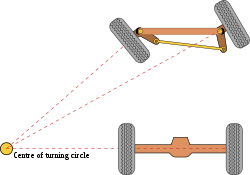
The intention of Ackermann geometry is to avoid the need for tyres to slip sideways when following the path around a curve.[2] The geometrical solution to this is for all wheels to have their axles arranged as radii of circles with a common centre point. As the rear wheels are fixed, this centre point must be on a line extended from the rear axle. Intersecting the axes of the front wheels on this line as well requires that the inside front wheel is turned, when steering, through a greater angle than the outside wheel. [2]
Rather than the preceding "turntable" steering, where both front wheels turned around a common pivot, each wheel gained its own pivot, close to its own hub. While more complex, this arrangement enhances controllability by avoiding large inputs from road surface variations being applied to the end of a long lever arm, as well as greatly reducing the fore-and-aft travel of the steered wheels. A linkage between these hubs pivots the two wheels together, and by careful arrangement of the linkage dimensions the Ackermann geometry could be approximated. This was achieved by making the linkage not a simple parallelogram, but by making the length of the track rod (the moving link between the hubs) shorter than that of the axle, so that the steering arms of the hubs appeared to "toe out". As the steering moved, the wheels turned according to Ackermann, with the inner wheel turning further.[2] If the track rod is placed ahead of the axle, it should instead be longer in comparison, thus preserving this same "toe out".
Design and choice of geometry
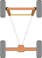

A simple approximation to perfect Ackermann steering geometry may be generated by moving the steering pivot points inward so as to lie on a line drawn between the steering kingpins and the centre of the rear axle.[2] The steering pivot points are joined by a rigid bar called the tie rod which can also be part of the steering mechanism, in the form of a rack and pinion for instance. With perfect Ackermann, at any angle of steering, the centre point of all of the circles traced by all wheels will lie at a common point. Note that this may be difficult to arrange in practice with simple linkages, and designers are advised to draw or analyse their steering systems over the full range of steering angles.
Modern cars do not use pure Ackermann steering, partly because it ignores important dynamic and compliant effects, but the principle is sound for low-speed manoeuvres. Some racing cars use reverse Ackermann geometry to compensate for the large difference in slip angle between the inner and outer front tyres while cornering at high speed. The use of such geometry helps reduce tyre temperatures during high-speed cornering but compromises performance in low-speed maneuvers.[3]
References
- ↑ Erasmus Darwin's Improved Design for Steering Carriages by Desmond King-Hele , 2002, The Royal Society, London. Accessed April 2008.
- 1 2 3 4 Norris, William (1906). "Steering". Modern Steam Road Wagons. Longmans. pp. 63–67.
- ↑ Milliken, William F, and Milliken, Douglas L: "Race Car Vehicle Dynamics", Page 715. SAE 1995 ISBN 1-56091-526-9
External links
- RcTek article about Ackermann steering geometry
- 2002 technical paper on Ackermann steering linkage design
- Ackerman? Or not? Does it matter?
- True Ackermann & Dynamic generated Ackermann
- Common fitting error on old Ford vehicles when tie rod is fitted in front of the axle
- Problems experienced that may be due to excessive Ackermann or insufficient Ackermann
- Ackermann Steering and Racing Circle (oval) Tracks, includes the toe out effect when Ackermann steering geometry is included and its use in racing