Amplitude modulation
| Passband modulation |
|---|
| Analog modulation |
| Digital modulation |
| Spread spectrum |
| See also |
Amplitude modulation (AM) is a modulation technique used in electronic communication, most commonly for transmitting information via a radio carrier wave. In amplitude modulation, the amplitude (signal strength) of the carrier wave is varied in proportion to the waveform being transmitted. That waveform may, for instance, correspond to the sounds to be reproduced by a loudspeaker, or the light intensity of television pixels. This technique contrasts with frequency modulation, in which the frequency of the carrier signal is varied, and phase modulation, in which its phase is varied.
AM was the earliest modulation method used to transmit voice by radio. It was developed during the first two decades of the 20th century beginning with Roberto Landell De Moura and Reginald Fessenden's radiotelephone experiments in 1900.[1] It remains in use today in many forms of communication; for example it is used in portable two way radios, VHF aircraft radio, Citizen's Band Radio, and in computer modems (in the form of QAM). "AM" is often used to refer to mediumwave AM radio broadcasting.
Forms of amplitude modulation
In electronics and telecommunications, modulation means varying some aspect of a higher frequency continuous wave carrier signal with an information-bearing modulation waveform, such as an audio signal which represents sound, or a video signal which represents images, so the carrier will "carry" the information. When it reaches its destination, the information signal is extracted from the modulated carrier by demodulation.
In amplitude modulation, the amplitude or "strength" of the carrier oscillations is what is varied. For example, in AM radio communication, a continuous wave radio-frequency signal (a sinusoidal carrier wave) has its amplitude modulated by an audio waveform before transmission. The audio waveform modifies the amplitude of the carrier wave and determines the envelope of the waveform. In the frequency domain, amplitude modulation produces a signal with power concentrated at the carrier frequency and two adjacent sidebands. Each sideband is equal in bandwidth to that of the modulating signal, and is a mirror image of the other. Standard AM is thus sometimes called "double-sideband amplitude modulation" (DSB-AM) to distinguish it from more sophisticated modulation methods also based on AM.
One disadvantage of all amplitude modulation techniques (not only standard AM) is that the receiver amplifies and detects noise and electromagnetic interference in equal proportion to the signal. Increasing the received signal to noise ratio, say, by a factor of 10 (a 10 decibel improvement), thus would require increasing the transmitter power by a factor of 10. This is in contrast to frequency modulation (FM) and digital radio where the effect of such noise following demodulation is strongly reduced so long as the received signal is well above the threshold for reception. For this reason AM broadcast is not favored for music and high fidelity broadcasting, but rather for voice communications and broadcasts (sports, news, talk radio etc.).
Another disadvantage of AM is that it is inefficient in power usage; at least two-thirds of the power is concentrated in the carrier signal. The carrier signal contains none of the original information being transmitted (voice, video, data, etc.). However its presence provides a simple means of demodulation using envelope detection, providing a frequency and phase reference to extract the modulation from the sidebands. In some modulation systems based on AM, a lower transmitter power is required through partial or total elimination of the carrier component, however receivers for these signals are more complex and costly. The receiver may regenerate a copy of the carrier frequency (usually as shifted to the intermediate frequency) from a greatly reduced "pilot" carrier (in reduced-carrier transmission or DSB-RC) to use in the demodulation process. Even with the carrier totally eliminated in double-sideband suppressed-carrier transmission, carrier regeneration is possible using a Costas phase-locked loop. This doesn't work however for single-sideband suppressed-carrier transmission (SSB-SC), leading to the characteristic "Donald Duck" sound from such receivers when slightly detuned. Single sideband is nevertheless used widely in amateur radio and other voice communications both due to its power efficiency and bandwidth efficiency (cutting the RF bandwidth in half compared to standard AM). On the other hand, in medium wave and short wave broadcasting, standard AM with the full carrier allows for reception using inexpensive receivers. The broadcaster absorbs the extra power cost to greatly increase potential audience.
An additional function provided by the carrier in standard AM, but which is lost in either single or double-sideband suppressed-carrier transmission, is that it provides an amplitude reference. In the receiver, the automatic gain control (AGC) responds to the carrier so that the reproduced audio level stays in a fixed proportion to the original modulation. On the other hand, with suppressed-carrier transmissions there is no transmitted power during pauses in the modulation, so the AGC must respond to peaks of the transmitted power during peaks in the modulation. This typically involves a so-called fast attack, slow decay circuit which holds the AGC level for a second or more following such peaks, in between syllables or short pauses in the program. This is very acceptable for communications radios, where compression of the audio aids intelligibility. However it is absolutely undesired for music or normal broadcast programming, where a faithful reproduction of the original program, including its varying modulation levels, is expected.
A trivial form of AM which can be used for transmitting binary data is on-off keying, the simplest form of amplitude-shift keying, in which ones and zeros are represented by the presence or absence of a carrier. On-off keying is likewise used by radio amateurs to transmit Morse code where it is known as continuous wave (CW) operation, even though the transmission is not strictly "continuous." A more complex form of AM, Quadrature amplitude modulation is now more commonly used with digital data, while making more efficient use of the available bandwidth.
ITU designations
In 1982, the International Telecommunication Union (ITU) designated the types of amplitude modulation:
| Designation | Description |
|---|---|
| A3E | double-sideband a full-carrier - the basic Amplitude modulation scheme |
| R3E | single-sideband reduced-carrier |
| H3E | single-sideband full-carrier |
| J3E | single-sideband suppressed-carrier |
| B8E | independent-sideband emission |
| C3F | vestigial-sideband |
| Lincompex | linked compressor and expander |
History
Although AM was used in a few crude experiments in multiplex telegraph and telephone transmission in the late 1800s,[2] the practical development of amplitude modulation is synonymous with the development between 1900 and 1920 of "radiotelephone" transmission, that is, the effort to send sound (audio) by radio waves. The first radio transmitters, called spark gap transmitters, transmitted information by wireless telegraphy, using different length pulses of carrier wave to spell out text messages in Morse code. They couldn't transmit audio because the carrier consisted of strings of damped waves, pulses of radio waves that declined to zero, that sounded like a buzz in receivers. In effect they were already amplitude modulated.
Continuous waves
The first AM transmission was made by Canadian researcher Reginald Fessenden on 23 December 1900 using a spark gap transmitter with a specially designed high frequency 10 kHz interrupter, over a distance of 1 mile (1.6 km) at Cobb Island, Maryland, USA. His first transmitted words were, "Hello. One, two, three, four. Is it snowing where you are, Mr. Thiessen?". The words were barely intelligible above the background buzz of the spark.
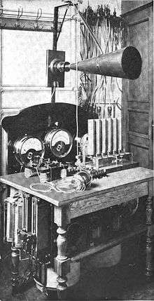
Fessenden was a significant figure in the development of AM radio. He was one of the first researchers to realize, from experiments like the above, that the existing technology for producing radio waves, the spark transmitter, was not usable for amplitude modulation, and that a new kind of transmitter, one that produced sinusoidal continuous waves, was needed. This was a radical idea at the time, because experts believed the impulsive spark was necessary to produce radio frequency waves, and Fessenden was ridiculed. He invented and helped develop one of the first continuous wave transmitters - the Alexanderson alternator, with which he made what is considered the first AM public entertainment broadcast on Christmas Eve, 1906. He also discovered the principle on which AM modulation is based, heterodyning, and invented one of the first detectors able to rectify and receive AM, the electrolytic detector or "liquid baretter", in 1902. Other radio detectors invented for wireless telegraphy, such as the Fleming valve (1904) and the crystal detector (1906) also proved able to rectify AM signals, so the technological hurdle was generating AM waves; receiving them was not a problem.
Early technologies
Early experiments in AM radio transmission, conducted by Fessenden, Valdamar Poulsen, Ernst Ruhmer, Quirino Majorana, Charles Harrold, and Lee De Forest, were hampered by the lack of a technology for amplification. The first practical continuous wave AM transmitters were based on either the huge, expensive Alexanderson alternator, developed 1906-1910, or versions of the Poulsen arc transmitter (arc converter), invented in 1903. The modifications necessary to transmit AM were clumsy and resulted in very low quality audio. Modulation was usually accomplished by a carbon microphone inserted directly in the antenna or ground wire; its varying resistance varied the current to the antenna. The limited power handling ability of the microphone severely limited the power of the first radiotelephones; many of the microphones were water-cooled.
Vacuum tubes
The discovery in 1912 of the amplifying ability of the Audion vacuum tube, invented in 1906 by Lee De Forest, solved these problems. The vacuum tube feedback oscillator, invented in 1912 by Edwin Armstrong and Alexander Meissner, was a cheap source of continuous waves and could be easily modulated to make an AM transmitter. Modulation did not have to be done at the output but could be applied to the signal before the final amplifier tube, so the microphone or other audio source didn't have to handle high power. Wartime research greatly advanced the art of AM modulation, and after the war the availability of cheap tubes sparked a great increase in the number of radio stations experimenting with AM transmission of news or music. The vacuum tube was responsible for the rise of AM radio broadcasting around 1920, the first electronic mass entertainment medium. Amplitude modulation was virtually the only type used for radio broadcasting until FM broadcasting began after World War 2.
At the same time as AM radio began, telephone companies such as AT&T were developing the other large application for AM: sending multiple telephone calls through a single wire by modulating them on separate carrier frequencies, called frequency division multiplexing.[2]
Single-sideband
John Renshaw Carson in 1915 did the first mathematical analysis of amplitude modulation, showing that a signal and carrier frequency combined in a nonlinear device would create two sidebands on either side of the carrier frequency, and passing the modulated signal through another nonlinear device would extract the original baseband signal.[2] His analysis also showed only one sideband was necessary to transmit the audio signal, and Carson patented single-sideband modulation (SSB) on 1 December 1915.[2] This more advanced variant of amplitude modulation was adopted by AT&T for longwave transatlantic telephone service beginning 7 January 1927. After WW2 it was developed by the military for aircraft communication.
Simplified analysis of standard AM

Consider a carrier wave (sine wave) of frequency fc and amplitude A given by:
- .

Let m(t) represent the modulation waveform. For this example we shall take the modulation to be simply a sine wave of a frequency fm, a much lower frequency (such as an audio frequency) than fc:
- ,

where M is the amplitude of the modulation. We shall insist that M<1 so that (1+m(t)) is always positive. If M>1 then overmodulation occurs and reconstruction of message signal from the transmitted signal would lead in loss of original signal. Amplitude modulation results when the carrier c(t) is multiplied by the positive quantity (1+m(t)):

![= [1 + m(t)]\cdot c(t) \,](../I/m/d59c65c5bb0696d1acde782242ae8a30f9f67991.svg)
![= [1 + M\cdot \cos(2 \pi f_m t + \phi)] \cdot A \cdot \sin(2 \pi f_c t)](../I/m/832d815150b2320100954829f25c9ad24632e544.svg)
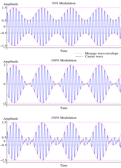
In this simple case M is identical to the modulation index, discussed below. With M=0.5 the amplitude modulated signal y(t) thus corresponds to the top graph (labelled "50% Modulation") in Figure 4.
Using prosthaphaeresis identities, y(t) can be shown to be the sum of three sine waves:
![y(t) = A\cdot \sin(2 \pi f_c t) + \begin{matrix}\frac{AM}{2} \end{matrix} \left[\sin(2 \pi (f_c + f_m) t + \phi) + \sin(2 \pi (f_c - f_m) t - \phi)\right].\,](../I/m/3ba6c481488d128f98d75d102d31147c507a0b6e.svg)
Therefore, the modulated signal has three components: the carrier wave c(t) which is unchanged, and two pure sine waves (known as sidebands) with frequencies slightly above and below the carrier frequency fc.
Spectrum

Of course a useful modulation signal m(t) will generally not consist of a single sine wave, as treated above. However, by the principle of Fourier decomposition, m(t) can be expressed as the sum of a number of sine waves of various frequencies, amplitudes, and phases. Carrying out the multiplication of 1+m(t) with c(t) as above then yields a result consisting of a sum of sine waves. Again the carrier c(t) is present unchanged, but for each frequency component of m at fi there are two sidebands at frequencies fc + fi and fc - fi. The collection of the former frequencies above the carrier frequency is known as the upper sideband, and those below constitute the lower sideband. In a slightly different way of looking at it, we can consider the modulation m(t) to consist of an equal mix of positive and negative frequency components (as results from a formal Fourier transform of a real valued quantity) as shown in the top of Fig. 2. Then one can view the sidebands as that modulation m(t) having simply been shifted in frequency by fc as depicted at the bottom right of Fig. 2 (formally, the modulated signal also contains identical components at negative frequencies, shown at the bottom left of Fig. 2 for completeness).
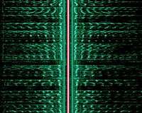
If we just look at the short-term spectrum of modulation, changing as it would for a human voice for instance, then we can plot the frequency content (horizontal axis) as a function of time (vertical axis) as in Fig. 3. It can again be seen that as the modulation frequency content varies, at any point in time there is an upper sideband generated according to those frequencies shifted above the carrier frequency, and the same content mirror-imaged in the lower sideband below the carrier frequency. At all times, the carrier itself remains constant, and of greater power than the total sideband power.
Power and spectrum efficiency
The RF bandwidth of an AM transmission (refer to Figure 2, but only considering positive frequencies) is twice the bandwidth of the modulating (or "baseband") signal, since the upper and lower sidebands around the carrier frequency each have a bandwidth as wide as the highest modulating frequency. Although the bandwidth of an AM signal is narrower than one using frequency modulation (FM), it is twice as wide as single-sideband techniques; it thus may be viewed as spectrally inefficient. Within a frequency band, only half as many transmissions (or "channels") can thus be accommodated. For this reason television employs a variant of single-sideband (known as vestigial sideband, somewhat of a compromise in terms of bandwidth) in order to reduce the required channel spacing.
Another improvement over standard AM is obtained through reduction or suppression of the carrier component of the modulated spectrum. In Figure 2 this is the spike in between the sidebands; even with full (100%) sine wave modulation, the power in the carrier component is twice that in the sidebands, yet it carries no unique information. Thus there is a great advantage in efficiency in reducing or totally suppressing the carrier, either in conjunction with elimination of one sideband (single-sideband suppressed-carrier transmission) or with both sidebands remaining (double sideband suppressed carrier). While these suppressed carrier transmissions are efficient in terms of transmitter power, they require more sophisticated receivers employing synchronous detection and regeneration of the carrier frequency. For that reason, standard AM continues to be widely used, especially in broadcast transmission, to allow for the use of inexpensive receivers using envelope detection. Even (analog) television, with a (largely) suppressed lower sideband, includes sufficient carrier power for use of envelope detection. But for communications systems where both transmitters and receivers can be optimized, suppression of both one sideband and the carrier represent a net advantage and are frequently employed.
Modulation index
The AM modulation index is a measure based on the ratio of the modulation excursions of the RF signal to the level of the unmodulated carrier. It is thus defined as:

where and are the modulation amplitude and carrier amplitude, respectively; the modulation amplitude is the peak (positive or negative) change in the RF amplitude from its unmodulated value. Modulation index is normally expressed as a percentage, and may be displayed on a meter connected to an AM transmitter.


So if , carrier amplitude varies by 50% above (and below) its unmodulated level, as is shown in the first waveform, below. For , it varies by 100% as shown in the illustration below it. With 100% modulation the wave amplitude sometimes reaches zero, and this represents full modulation using standard AM and is often a target (in order to obtain the highest possible signal to noise ratio) but mustn't be exceeded. Increasing the modulating signal beyond that point, known as overmodulation, causes a standard AM modulator (see below) to fail, as the negative excursions of the wave envelope cannot become less than zero, resulting in distortion ("clipping") of the received modulation. Transmitters typically incorporate a limiter circuit to avoid overmodulation, and/or a compressor circuit (especially for voice communications) in order to still approach 100% modulation for maximum intelligibility above the noise. Such circuits are sometimes referred to as a vogad.


However it is possible to talk about a modulation index exceeding 100%, without introducing distortion, in the case of double-sideband reduced-carrier transmission. In that case, negative excursions beyond zero entail a reversal of the carrier phase, as shown in the third waveform below. This cannot be produced using the efficient high-level (output stage) modulation techniques (see below) which are widely used especially in high power broadcast transmitters. Rather, a special modulator produces such a waveform at a low level followed by a linear amplifier. What's more, a standard AM receiver using an envelope detector is incapable of properly demodulating such a signal. Rather, synchronous detection is required. Thus double-sideband transmission is generally not referred to as "AM" even though it generates an identical RF waveform as standard AM as long as the modulation index is below 100%. Such systems more often attempt a radical reduction of the carrier level compared to the sidebands (where the useful information is present) to the point of double-sideband suppressed-carrier transmission where the carrier is (ideally) reduced to zero. In all such cases the term "modulation index" loses its value as it refers to the ratio of the modulation amplitude to a rather small (or zero) remaining carrier amplitude.
Modulation methods
Modulation circuit designs may be classified as low- or high-level (depending on whether they modulate in a low-power domain—followed by amplification for transmission—or in the high-power domain of the transmitted signal).[3]
Low-level generation
In modern radio systems, modulated signals are generated via digital signal processing (DSP). With DSP many types of AM are possible with software control (including DSB with carrier, SSB suppressed-carrier and independent sideband, or ISB). Calculated digital samples are converted to voltages with a digital to analog converter, typically at a frequency less than the desired RF-output frequency. The analog signal must then be shifted in frequency and linearly amplified to the desired frequency and power level (linear amplification must be used to prevent modulation distortion).[4] This low-level method for AM is used in many Amateur Radio transceivers.[5]
AM may also be generated at a low level, using analog methods described in the next section.
High-level generation
High-power AM transmitters (such as those used for AM broadcasting) are based on high-efficiency class-D and class-E power amplifier stages, modulated by varying the supply voltage.[6]
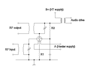
Older designs (for broadcast and amateur radio) also generate AM by controlling the gain of the transmitter’s final amplifier (generally class-C, for efficiency). The following types are for vacuum tube transmitters (but similar options are available with transistors):[7]
- Plate modulation: In plate modulation, the plate voltage of the RF amplifier is modulated with the audio signal. The audio power requirement is 50 percent of the RF-carrier power.
- Heising (constant-current) modulation: RF amplifier plate voltage is fed through a “choke” (high-value inductor). The AM modulation tube plate is fed through the same inductor, so the modulator tube diverts current from the RF amplifier. The choke acts as a constant current source in the audio range. This system has a low power efficiency.
- Control grid modulation: The operating bias and gain of the final RF amplifier can be controlled by varying the voltage of the control grid. This method requires little audio power, but care must be taken to reduce distortion.
- Clamp tube (screen grid) modulation: The screen-grid bias may be controlled through a “clamp tube”, which reduces voltage according to the modulation signal. It is difficult to approach 100-percent modulation while maintaining low distortion with this system.
- Doherty modulation: One tube provides the power under carrier conditions and another operates only for positive modulation peaks. Overall efficiency is good, and distortion is low.
- Outphasing modulation: Two tubes are operated in parallel, but partially out of phase with each other. As they are differentially phase modulated their combined amplitude is greater or smaller. Efficiency is good and distortion low when properly adjusted.
- Pulse width modulation (PWM) or Pulse duration modulation (PDM): A highly efficient high voltage power supply is applied to the tube plate. The output voltage of this supply is varied at an audio rate to follow the program. This system was pioneered by Hilmer Swanson and has a number of variations, all of which achieve high efficiency and sound quality.
Demodulation methods
The simplest form of AM demodulator consists of a diode which is configured to act as envelope detector. Another type of demodulator, the product detector, can provide better-quality demodulation with additional circuit complexity.
See also
- AM radio
- AM stereo
- Mediumwave band used for AM broadcast radio
- Longwave band used for AM broadcast radio
- Frequency modulation
- Shortwave radio almost universally uses AM, narrow FM occurring above 25 MHz.
- Modulation, for a list of other modulation techniques
- Amplitude modulation signalling system (AMSS), a digital system for adding low bitrate information to an AM signal.
- Sideband, for some explanation of what this is.
- Types of radio emissions, for the emission types designated by the ITU
- Airband
- Citizen's Band Radio
- Quadrature amplitude modulation
- DSB-SC
References
- Notes
- ↑ http://www.aminharadio.com/radio/files/Artigo-Revista-PCP-USA.pdf
- 1 2 3 4 Bray, John (2002). Innovation and the Communications Revolution: From the Victorian Pioneers to Broadband Internet. Inst. of Electrical Engineers. pp. 59, 61–62. ISBN 0852962185.
- ↑ A.P.Godse and U.A.Bakshi (2009). Communication Engineering. Technical Publications. p. 36. ISBN 978-81-8431-089-4.
- ↑ Silver, Ward, ed. (2011). "Ch. 15 DSP and Software Radio Design". The ARRL Handbook for Radio Communications (Eighty-eighth ed.). American Radio Relay League. ISBN 978-0-87259-096-0.
- ↑ Silver, Ward, ed. (2011). "Ch. 14 Transceivers". The ARRL Handbook for Radio Communications (Eighty-eighth ed.). American Radio Relay League. ISBN 978-0-87259-096-0.
- ↑ Frederick H. Raab; et al. (May 2003). "RF and Microwave Power Amplifier and Transmitter Technologies - Part 2". High Frequency Design: 22ff.
- ↑ Laurence Gray and Richard Graham (1961). Radio Transmitters. McGraw-Hill. pp. 141ff.
- Sources
- Newkirk, David and Karlquist, Rick (2004). Mixers, modulators and demodulators. In D. G. Reed (ed.), The ARRL Handbook for Radio Communications (81st ed.), pp. 15.1–15.36. Newington: ARRL. ISBN 0-87259-196-4.
External links
- Amplitude Modulation by Jakub Serych, Wolfram Demonstrations Project.
- Amplitude Modulation, by S Sastry.
- Amplitude Modulation, an introduction by Federation of American Scientists.
- Amplitude Modulation tutorial video with example transmitter circuit.
- Amplitude Modulation tutorial including related topics of modulators, demodulators, etc . .