Electronic oscillator

An electronic oscillator is an electronic circuit that produces a periodic, oscillating electronic signal, often a sine wave or a square wave.[1][2] Oscillators convert direct current (DC) from a power supply to an alternating current (AC) signal. They are widely used in many electronic devices. Common examples of signals generated by oscillators include signals broadcast by radio and television transmitters, clock signals that regulate computers and quartz clocks, and the sounds produced by electronic beepers and video games.[1]
Oscillators are often characterized by the frequency of their output signal:
- A low-frequency oscillator (LFO) is an electronic oscillator that generates a frequency below ≈20 Hz. This term is typically used in the field of audio synthesizers, to distinguish it from an audio frequency oscillator.
- An audio oscillator produces frequencies in the audio range, about 16 Hz to 20 kHz.[2]
- An RF oscillator produces signals in the radio frequency (RF) range of about 100 kHz to 100 GHz.[2]
Oscillators designed to produce a high-power AC output from a DC supply are usually called inverters.
There are two main types of electronic oscillator: the linear or harmonic oscillator and the nonlinear or relaxation oscillator.[2][3]
.jpg)
Harmonic oscillator
The harmonic, or linear, oscillator produces a sinusoidal output.[2][3] There are two types:
Feedback oscillator
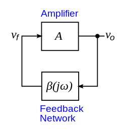
The most common form of linear oscillator is an electronic amplifier such as a transistor or op amp connected in a feedback loop with its output fed back into its input through a frequency selective electronic filter to provide positive feedback. When the power supply to the amplifier is first switched on, electronic noise in the circuit provides a non-zero signal to get oscillations started. The noise travels around the loop and is amplified and filtered until very quickly it converges on a sine wave at a single frequency.
Feedback oscillator circuits can be classified according to the type of frequency selective filter they use in the feedback loop:[2][3]
- In an RC oscillator circuit, the filter is a network of resistors and capacitors.[2][3] RC oscillators are mostly used to generate lower frequencies, for example in the audio range. Common types of RC oscillator circuits are the phase shift oscillator and the Wien bridge oscillator.
- In an LC oscillator circuit, the filter is a tuned circuit (often called a tank circuit; the tuned circuit is a resonator) consisting of an inductor (L) and capacitor (C) connected together.[2][3] Charge flows back and forth between the capacitor's plates through the inductor, so the tuned circuit can store electrical energy oscillating at its resonant frequency. There are small losses in the tank circuit, but the amplifier compensates for those losses and supplies the power for the output signal. LC oscillators are often used at radio frequencies,[2] when a tunable frequency source is necessary, such as in signal generators, tunable radio transmitters and the local oscillators in radio receivers. Typical LC oscillator circuits are the Hartley, Colpitts[2] and Clapp circuits.

- In a crystal oscillator circuit the filter is a piezoelectric crystal (commonly a quartz crystal).[2][3] The crystal mechanically vibrates as a resonator, and its frequency of vibration determines the oscillation frequency. Crystals have very high Q-factor and also better temperature stability than tuned circuits, so crystal oscillators have much better frequency stability than LC or RC oscillators. Crystal oscillators are the most common type of linear oscillator, used to stabilize the frequency of most radio transmitters, and to generate the clock signal in computers and quartz clocks. Crystal oscillators often use the same circuits as LC oscillators, with the crystal replacing the tuned circuit;[2] the Pierce oscillator circuit is also commonly used. Quartz crystals are generally limited to frequencies of 30 MHz or below.[2] Other types of resonator, dielectric resonators and surface acoustic wave (SAW) devices, are used to control higher frequency oscillators, up into the microwave range. For example, SAW oscillators are used to generate the radio signal in cell phones.
Negative resistance oscillator

In addition to the feedback oscillators described above, which use two-port amplifying active elements such as transistors and op amps, linear oscillators can also be built using one-port (two terminal) devices with negative resistance,[2][3] such as magnetron tubes, tunnel diodes, lambda diodes and Gunn diodes. Negative resistance oscillators are usually used at high frequencies in the microwave range and above, since at these frequencies feedback oscillators perform poorly due to excessive phase shift in the feedback path.
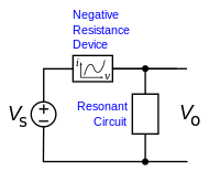
In negative resistance oscillators, a resonant circuit, such as an LC circuit, crystal, or cavity resonator, is connected across a device with negative differential resistance, and a DC bias voltage is applied to supply energy. A resonant circuit by itself is "almost" an oscillator; it can store energy in the form of electronic oscillations if excited, but because it has electrical resistance and other losses the oscillations are damped and decay to zero. The negative resistance of the active device cancels the (positive) internal loss resistance in the resonator, in effect creating a resonator with no damping, which generates spontaneous continuous oscillations at its resonant frequency.
The negative resistance oscillator model is not limited to one-port devices like diodes; feedback oscillator circuits with two-port amplifying devices such as transistors and tubes also have negative resistance.[4][5][6] At high frequencies, transistors and FETs do not need a feedback loop, but with certain loads applied to one port can become unstable at the other port and show negative resistance due to internal feedback, causing them to oscillate.[4][5][7] So high frequency oscillators in general are designed using negative resistance techniques.[4][5][6]
Some of the many harmonic oscillator circuits are listed below:
| Device | Frequency |
|---|---|
| Triode vacuum tube | ~1 GHz |
| Bipolar transistor (BJT) | ~20 GHz |
| Heterojunction Bipolar Transistor (HBT) | ~50 GHz |
| Metal Semiconductor Field Effect Transistor (MESFET) | ~100 GHz |
| Gunn diode, fundamental mode | ~100 GHz |
| Magnetron tube | ~100 GHz |
| High Electron Mobility Transistor (HEMT) | ~200 GHz |
| Klystron tube | ~200 GHz |
| Gunn diode, harmonic mode | ~200 GHz |
| IMPATT diode | ~300 GHz |
| Gyrotron tube | ~300 GHz |
- Armstrong oscillator
- Clapp oscillator
- Colpitts oscillator
- Cross-coupled oscillator
- Dynatron oscillator
- Hartley oscillator
- Meissner oscillator
- Opto-electronic oscillator
- Pierce oscillator
- Phase-shift oscillator
- Robinson oscillator
- Tri-tet oscillator
- Vackář oscillator
- Wien bridge oscillator
Relaxation oscillator
A nonlinear or relaxation oscillator produces a non-sinusoidal output, such as a square, sawtooth or triangle wave.[3] It consists of an energy-storing element (a capacitor or, more rarely, an inductor) and a nonlinear switching device (a latch, Schmitt trigger, or negative resistance element) connected in a feedback loop. The switching device periodically charges and discharges the energy stored in the storage element thus causing abrupt changes in the output waveform.
Square-wave relaxation oscillators are used to provide the clock signal for sequential logic circuits such as timers and counters, although crystal oscillators are often preferred for their greater stability. Triangle wave or sawtooth oscillators are used in the timebase circuits that generate the horizontal deflection signals for cathode ray tubes in analogue oscilloscopes and television sets. They are also used in voltage controlled oscillators (VCOs), inverters and switching power supplies, dual slope analog to digital converters (ADCs), and in function generators to generate square and triangle waves for testing equipment. In general, relaxation oscillators are used at lower frequencies and have poorer frequency stability than linear oscillators.
Ring oscillators are built of a ring of active delay stages. Generally the ring has an odd number of inverting stages, so that there is no single stable state for the internal ring voltages. Instead, a single transition propagates endlessly around the ring.
Some of the more common relaxation oscillator circuits are listed below:
Voltage-controlled oscillator (VCO)
An oscillator can be designed so that the oscillation frequency can be varied over some range by an input voltage or current. These voltage controlled oscillators are widely used in phase-locked loops, in which the oscillator's frequency can be locked to the frequency of another oscillator. These are ubiquitous in modern communications circuits, used in filters, modulators, demodulators, and forming the basis of frequency synthesizer circuits which are used to tune radios and televisions.
Radio frequency VCOs are usually made by adding a varactor diode to the tuned circuit or resonator in an oscillator circuit. Changing the DC voltage across the varactor changes its capacitance, which changes the resonant frequency of the tuned circuit. Voltage controlled relaxation oscillators can be constructed by charging and discharging the energy storage capacitor with a voltage controlled current source. Increasing the input voltage increases the rate of charging the capacitor, decreasing the time between switching events.
History
One of the first electronic oscillators was an oscillating arc built by Elihu Thomson in 1892.[8][9] Thomson's oscillator placed an LC tuned circuit in parallel with the arc, used metal electrodes, and included a magnetic blowout. Independently in the same year, George Francis Fitzgerald realized that if the damping resistance in a resonant circuit could be made zero or negative, it would produce oscillations, and tried unsuccessfully to build a negative resistance oscillator with a dynamo, what would now be called a parametric oscillator.[10][11] The arc oscillator was rediscovered and popularized by William Duddell in 1900.[12][13] Electric arcs were used to provide illumination in the 19th century, but the arc current was unstable and they often produced hissing, humming or howling sounds.[11] Duddell, a student at London Technical College, investigated this effect. He attached an LC circuit to the electrodes of an arc lamp, and the negative resistance of the arc excited audio frequency oscillations in the tuned circuit at its resonant frequency.[11] Some of the energy was radiated as sound waves by the arc, producing a musical tone. To demonstrate his oscillator before the London Institute of Electrical Engineers, Duddell wired a series of tuned circuits to the arc and played a tune, "God Save The Queen".[11] Duddell wasn't able to generate frequencies above the audio range with his "singing arc", but in 1902 Danish physicists Valdemar Poulsen and P. O. Pederson were able to increase the frequency produced into the radio range, inventing the Poulsen arc radio transmitter, the first continuous wave radio transmitter, which was used through the 1920s.[14][15][16]
The vacuum tube feedback oscillator was invented around 1912, when it was discovered that feedback ("regeneration") in the recently invented audion vacuum tube could produce oscillations. At least six researchers independently made this discovery and can be said to have some role in the invention.[17][18] In the summer of 1912, Edwin Armstrong observed oscillations in audion radio receiver circuits[19] and went on to use positive feedback in his invention of the regenerative receiver.[20][21] German Alexander Meissner independently discovered positive feedback and invented oscillators in March 1913.[19][22] Irving Langmuir at General Electric observed feedback in 1913.[22] Fritz Lowenstein may have preceded the others with a crude oscillator in late 1911.[23] In Britain, H. J. Round patented amplifying and oscillating circuits in 1913.[19] In August 1912, Lee De Forest, the inventor of the audion, had also observed oscillations in his amplifiers, but he didn't understand its significance and tried to eliminate it[24][25] until he read Armstrong's patents in 1914,[26] which he promptly challenged.[27] Armstrong and De Forest fought a protracted legal battle over the rights to the "regenerative" oscillator circuit[27][28] which has been called "the most complicated patent litigation in the history of radio".[29] De Forest ultimately won before the Supreme Court in 1934 on technical grounds, but most sources regard Armstrong's claim as the stronger one.[25][27]
The first and most widely used relaxation oscillator circuit, the astable multivibrator, was invented in 1917 by French engineers Henri Abraham and Eugene Bloch.[30][31][32] They called their cross-coupled, dual vacuum tube circuit a multivibrateur because the square-wave signal it produced was rich in harmonics,[31][32] compared to the sinusoidal signal of other vacuum tube oscillators.
Vacuum tube feedback oscillators became the basis of radio transmission by 1920. However the triode vacuum tube oscillator performed poorly above 300 MHz because of interelectrode capacitance. To reach higher frequencies, new "transit time" (velocity modulation) vacuum tubes were developed, in which electrons traveled in "bunches" through the tube. The first of these was the Barkhausen-Kurz oscillator (1920), the first tube to produce power in the UHF range. The most important and widely used were the klystron (R. and S. Varian, 1937) and the cavity magnetron (J. Randall and H. Boot, 1940).
Mathematical conditions for feedback oscillations, now called the Barkhausen criterion, were derived by Heinrich Georg Barkhausen in 1921. The first analysis of a nonlinear electronic oscillator model, the Van der Pol oscillator, was done by Balthasar van der Pol in 1927.[33] He showed that the stability of the oscillations (limit cycles) in actual oscillators was due to the nonlinearity of the amplifying device. He originated the term "relaxation oscillation" and was first to distinguish between linear and relaxation oscillators. Further advances in mathematical analysis of oscillation were made by Hendrik Wade Bode and Harry Nyquist[34] in the 1930s. In 1969 K. Kurokawa derived necessary and sufficient conditions for oscillation in negative resistance circuits,[35] which form the basis of modern microwave oscillator design.[7]
See also
References
- 1 2 Snelgrove, Martin (2011). "Oscillator". McGraw-Hill Encyclopedia of Science and Technology, 10th Ed., Science Access online service. McGraw-Hill. Retrieved March 1, 2012.
- 1 2 3 4 5 6 7 8 9 10 11 12 13 14 Chattopadhyay, D. (2006). Electronics (fundamentals And Applications). New Age International. pp. 224–225. ISBN 81-224-1780-9.
- 1 2 3 4 5 6 7 8 Garg, Rakesh Kumar; Ashish Dixit; Pavan Yadav (2008). Basic Electronics. Firewall Media. p. 280. ISBN 8131803023.
- 1 2 3 Kung, Fabian Wai Lee (2009). "Lesson 9: Oscillator Design" (PDF). RF/Microwave Circuit Design. Prof. Kung's website, Multimedia University. Retrieved October 17, 2012. External link in
|work=(help), Sec. 3 Negative Resistance Oscillators, p. 9-10, 14 - 1 2 3 4 Räisänen, Antti V.; Arto Lehto (2003). Radio Engineering for Wireless Communication and Sensor Applications. USA: Artech House. pp. 180–182. ISBN 1580535429.
- 1 2 Ellinger, Frank (2008). Radio Frequency Integrated Circuits and Technologies, 2nd Ed. USA: Springer. pp. 391–394. ISBN 3540693246.
- 1 2 Maas, Stephen A. (2003). Nonlinear Microwave and RF Circuits, 2nd Ed. Artech House. pp. 542–544. ISBN 1580534848.
- ↑ Morse 1925, p. 23
- ↑ US 500630, Thomson, Elihu, "Method of and Means for Producing Alternating Currents", published 18 July 1892, issued 4 July 1893
- ↑ G. Fitzgerald, On the Driving of Electromagnetic Vibrations by Electromagnetic and Electrostatic Engines, read at the January 22, 1892 meeting of the Physical Society of London, in Larmor, Joseph, ed. (1902). The Scientific Writings of the late George Francis Fitzgerald. London: Longmans, Green and Co. pp. 277–281.
- 1 2 3 4 Hong, Sungook (2001). Wireless: From Marconi's Black-Box to the Audion. MIT Press. ISBN 0262082985., pp. 161–165
- ↑ Morse 1925, pp. 80–81
- ↑ GB 190021629, Duddell, William du Bois, "Improvements in and connected with Means for the Conversion of Electrical Energy, Derived from a Source of Direct Current, into Varying or Alternating Currents", published 29 Nov 1900, issued 23 Nov 1901
- ↑ Morse 1925, p. 31
- ↑ GB 190315599, Poulsen, "Improvements relating to the Production of Alternating Electric Currents", issued 14 July 1904
- ↑ US 789449, Poulsen, Valdemar, "Method of Producing Alternating Currents with a High Number of Vibrations", issued 9 May 1905
- ↑ Hempstead, Colin; William E. Worthington (2005). Encyclopedia of 20th-Century Technology. 2. Taylor & Francis. p. 648. ISBN 1579584640.
- ↑ Hong 2001, p. 156
- 1 2 3 Fleming, John Ambrose (1919). The Thermionic Valve and its Developments in Radiotelegraphy and Telephony. London: The Wireless Press. pp. 148–155.
- ↑ Hong, Sungook (2003). "A history of the regeneration circuit: From invention to patent litigation" (PDF). IEEE. Retrieved August 29, 2012., pp. 9–10
- ↑ Armstrong, Edwin H. (September 1915). "Some recent developments in the Audion receiver" (PDF). Proc. of the IRE. New York: Institute of Radio Engineers. 3 (9): 215–247. doi:10.1109/jrproc.1915.216677. Retrieved August 29, 2012.
- 1 2 Hong 2003, p. 13
- ↑ Hong 2003, p. 5
- ↑ Hong 2003, pp. 6–7
- 1 2 Hijiya, James A. (1992). Lee De Forest and the Fatherhood of Radio. Lehigh University Press. pp. 89–90. ISBN 0934223238.
- ↑ Hong 2003, p. 14
- 1 2 3 Nahin, Paul J. (2001). The Science of Radio: With Matlab and Electronics Workbench Demonstration, 2nd Ed. Springer. p. 280. ISBN 0387951504.
- ↑ Hong 2001, pp. 181–189
- ↑ Hong 2003, p. 2
- ↑ Abraham, H.; E. Bloch (1919). "Measurement of period of high frequency oscillations". Comptes Rendus. French Academy of Sciences. 168: 1105.
- 1 2 Glazebrook, Richard (1922). A Dictionary of Applied Physics, Vol. 2: Electricity. London: Macmillan and Co. Ltd. pp. 633–634.
- 1 2 Calvert, James B. (2002). "The Eccles-Jordan Circuit and Multivibrators". Dr. J. B. Calvert website, Univ. of Denver. Retrieved May 15, 2013. External link in
|publisher=(help) - ↑ Van der Pol, Balthazar (1927). "On relaxation-oscillations". The London, Edinburgh and Dublin Philosophical Magazine. 2 (7): 978–992. doi:10.1080/14786442608564127.
- ↑ Nyquist, H. (January 1932). "Regeneration Theory" (PDF). Bell System Tech. J. USA: American Tel. & Tel. 11 (1): 126–147. doi:10.1002/j.1538-7305.1932.tb02344.x. Retrieved December 5, 2012. on Alcatel-Lucent website
- ↑ Kurokawa, K. (July 1969). "Some Basic Characteristics of Broadband Negative Resistance Oscillator Circuits" (PDF). Bell System Tech. J. USA: American Tel. & Tel. 48 (6): 1937–1955. doi:10.1002/j.1538-7305.1969.tb01158.x. Retrieved December 8, 2012. Eq. 10 is necessary condition for oscillation, eq. 12 is sufficient condition.
- Morse, A. H. (1925), Radio: Beam and Broadcast: Its story and patents, London: Ernest Benn. History of radio in 1925. Oscillator claims 1912; De Forest and Armstrong court case cf p. 45. Telephone hummer/oscillator by A. S. Hibbard in 1890 (carbon microphone has power gain); Larsen "used the same principle in the production of alternating current from a direct current source"; accidental development of vacuum tube oscillator; all at p. 86. Von Arco and Meissner first to recognize application to transmitter; Round for first transmitter; nobody patented triode transmitter at p. 87.
Further reading
- Ulrich Rohde, Ajay Poddar, and Georg Bock, The Design of Modern Microwave Oscillators for Wireless Applications: Theory and Optimization, (543-pages) John Wiley & Sons, 2005, ISBN 0-471-72342-8.
- E. Rubiola, Phase Noise and Frequency Stability in Oscillators Cambridge University Press, 2008. ISBN 978-0-521-88677-2.
External links
| Wikimedia Commons has media related to Electronic oscillators. |