Bar stock
Bar stock, also colloquially known as billet,[1] is a common form of raw purified metal, used by industry to manufacture metal parts and products.
Process and types
Most metal produced by a steel mill or aluminium plant is formed (via rolling or extrusion) into long continuous strips of various size and shape. These strips are cut at regular intervals and allowed to cool, each segment becoming a piece of bar stock. A good analogy is pasta-making, in which lumps of dough are extruded into various cross-sectional shapes; cut into lengths; and then dried in that form. The cross-sectional shapes of pasta vary from simple bar or tube shapes (such as linguine or penne) to more elaborate extrusions (such as rotelle, fiori, or rotini). The same is true of metal bar stock. The most common shapes are round bar (also called rod), rectangular bar (including square bar, the special case of equal sides), and hexagonal bar (usually called hex bar for short). Tube and pipe are similar, but have hollow centers and are traditionally not called "bar" in industrial usage. (However, a product called hollow bar, essentially tube but with custom-orderable OD and ID and thus custom wall thickness, is marketed for lathe bar work which can benefit from obviation of drilling and rough boring.) Also similar in concept, but not called "bar", are the common structural shapes such as angle stock and channel stock. These are commonly available in steel and aluminum; the names "angle iron" and "channel iron" are still commonly used (informally) even though their literal namesake, wrought iron, has been replaced by steel and aluminum for most uses.
In a machine shop, bar stock and plate are often called billet, although in a rolling mill, that word refers to a piece of metal that has not yet been rolled into bar.
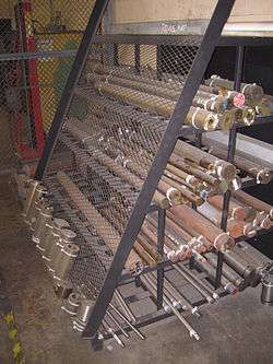
A machine shop typically has a storage area containing a large variety of bar stock. To create a metal component, a bar of sufficient volume is selected from storage and brought to the machining area. This piece may then be sawed, milled, drilled, turned, or ground to remove material and create the final shape. In turning, for large-diameter work (typically more than 100 millimetres (3.9 in), although there is no universal threshold), a piece of the bar is cut off using a horizontal bandsaw to create a blank for each part. The blanks are then fed into a chucking lathe (chucker) which chucks each one in turn. For smaller-diameter work, the entire length of bar stock is more often fed through the spindle of the lathe. The entire bar rotates with the spindle during the part-machining cycle. When the cycle ends and one part is done, the chuck opens, the bar is pulled or pushed forward ("fed") by any of various automatic means, the chuck closes, and the next cycle begins. The last step of the cycle is to cut off the machined part from the bar, which is called "parting it off" and is achieved with a "cutoff" or "part-off" tool, a tool bit that grooves the bar all the way down to the centreline, causing the part to fall off. Then the cycle repeats.
The not-yet-cut bar protruding from the back of the spindle, rotating quickly, can present a safety hazard if it is sticking out too far and unconstrained from bending. Thus sometimes long bars must be sawn into shorter bars before being fed as "bar work" (which is the term for such work).
CNC lathes and screw machines have accessories called "bar feeders", which hold, guide, and feed the bar as commanded by the CNC control. More advanced machines may have a "bar loader" which holds multiple bars and feeds them one at a time into the bar feeder. Bar loaders are like magazines for part blanks (or pallets for milling work) in that they allow lights-out machining. The bar loader is filled with bars (or the magazine or pallet with part blanks) during working hours, and then it runs during the night unattended. Given that there is no human around to detect if something went wrong and the machine should stop, there are various kinds of sensors that are used to detect this, such as load meters, infrared beams, and, in recent years, webcams, which are placed inside the machine tool's enclosure and allow remote viewing of the cutting action.
Standard sizes throughout a supply chain
To stock every possible size of bar stock (every possible fraction of a millimetre or inch in diameter or thickness) is impossible. Thus, bar stock is stocked by metals supply houses in various standard sizes, arrayed in discrete steps. For example, round bar with diameters of even millimetres (or in the USA, on the eighths of an inch) can usually be ordered from standing stock. Bar diameters of nonstandard sizes can also be obtained, but only as a separate mill run from the rolling mill. Thus they are much more expensive than the standard sizes, can take much longer delivery time, and are not desirable as inventory for the supply house or the machine shop (because the chance of selling or using any particular custom size is slim).
Sometimes it is necessary that the bar not be very much larger than the intended part, because the metallurgical properties of some metal alloys in some finishing processes may vary by how far inside the bar the metal lies. Thus an engineering drawing will specify a certain size (or a maximum size) that the bar may start out as. These specs face the aforementioned limitation of stocking sizes versus custom mill runs; standard sizes are used wherever possible to avoid wasted expense and needless delays.
Drill rod
Drill rod is tool steel round stock ground to a tight tolerance diameter; it is usually ±0.0005 in (±0.013 mm). In the UK the name "silver steel" is often synonymous and sometimes hyponymous. Its origin was in reference to the shiny ground appearance (not to any silver alloying content). Drill rod diameters range from 0.0135 to 1.5 in (0.34 to 38.10 mm); in the United States diameters smaller than 27⁄64th of an inch are made in letter drill sizes and number drill sizes, in addition to fractional sizes. Lengths are usually one or three feet (0.3 or 0.9 m). It is commonly used to make drill bits, taps, reamers, punches, dowel pins, and shafts.[2] Note that the numbered sizes are different from the drill numbered sizes starting at 52. These sizes are:
|
|
|
|
Drill blanks have an undersize tolerance of +0/−0.0002 in, while reamer blanks have an oversize tolerance of −0/+0.0002 in.
Some mills also sell square stock that is held to the same tolerances under the name "drill rod".[2]
Commonly available material grades in the U.S. are A2, D2, M2, M42, O1, S7, W1, and high speed steel (including M2/M7).[3]
Ground flat stock
Ground flat stock is annealed steel that has been ground to close tolerances (compare to drill rod). There are four types of materials available: O-1 tool steel, A-2 tool steel, A-6 tool steel, and 1018 steel (low-carbon or low-carb steel). Lengths are either 18 or 36 in (457 or 914 mm) long, various widths up to 16 in (406 mm) are available, and thicknesses range from 1⁄64 to 2.875 in (0.40 to 73.03 mm).[4][5][6]
Some geometrical sizes are known as gauge plate.[7]
References
- ↑ Brafield, Evans (February 2009), What's Billet?, archived from the original on 2010-05-03, retrieved 03-05-2010. Check date values in:
|access-date=(help) - 1 2 Brady, George S.; Clauser, Henry R.; Vaccari, John A. (2002). Materials Handbook (15th ed.). McGraw-Hill. p. 322. ISBN 978-0-07-136076-0.
- ↑ McMaster-Carr catalog (115th ed.), McMaster-Carr, pp. 3641–3653, retrieved 2010-12-19.
- ↑ Burroughs, John (March 1968), "What You Should Know About Ground Flat Stock", Popular Mechanics, 129 (3): 182–185, ISSN 0032-4558
- ↑ Starrett catalog 32 (PDF), p. 624, archived (PDF) from the original on 2010-12-22, retrieved 2010-12-22.
- ↑ Starrett catalog 32 (PDF), p. 634, archived (PDF) from the original on 2010-12-22, retrieved 2010-12-22.
- ↑ Nesbitt, Brian (2007). Handbook of Valves and Actuators. Butterworth-Heinemann. p. 17. ISBN 978-1-85617-494-7.