Barton Swing Aqueduct
| Barton Swing Aqueduct | |
|---|---|
|
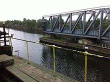
The aqueduct in the closed position | |
| OS grid reference | |
| Carries | Bridgewater Canal |
| Crosses | Manchester Ship Canal |
| Locale | Barton upon Irwell |
| Heritage status | Grade II* |
| Characteristics | |
| Total length | 330 feet (101 m) |
| Traversable? | Only narrowboats |
| Towpaths | None |
| Number of spans | Two (Central Pivot) |
| History | |
| Designer | Sir Edward Leader Williams |
| Construction end | 1893 |
| Opened | 1894 |
Coordinates: 53°28′29″N 2°21′08″W / 53.4748°N 2.3521°W
The Barton Swing Aqueduct is a moveable navigable aqueduct in Barton upon Irwell, Greater Manchester, England. It carries the Bridgewater Canal across the Manchester Ship Canal. The swinging action allows large vessels using the ship canal to pass underneath and smaller narrowboats to cross over the top. The aqueduct, the first and only swing aqueduct in the world,[1] is a Grade II* listed building,[2] and considered a major feat of Victorian civil engineering.[2][3] Designed by Sir Edward Leader Williams and built by Andrew Handyside and Company of Derby, the swing bridge opened in 1894 and remains in regular use.
History

The Barton Swing Aqueduct is a direct replacement for the earlier Barton Aqueduct, a masonry structure crossing the River Irwell and completed in 1761. The construction of the Manchester Ship Canal in the 1890s necessitated the replacement of this structure, as the height of ships using the new ship canal was too great to pass under the old aqueduct.[5] An alternative scheme involving the use of a double lock flight was rejected, because of the need to conserve water in the Bridgewater Canal above.[6]
The new aqueduct was designed by Sir Edward Leader Williams,[2] engineer to the Manchester Ship Canal Company, and was built by Andrew Handyside and Company of Derby. The first barge crossed the new aqueduct on 21 August 1893, and it opened to commercial traffic on 1 January 1894.[7] Williams was also involved with the Anderton Boat Lift, another moving canal structure in the region.
Construction
Construction work began in 1890, with the demolition of a Roman Catholic school on the south bank of the ship canal. The scale of the operation meant that the course of the River Irwell had to be temporarily diverted around the site, so that the central island could be built on dry land.[8]
Operation
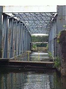
The aqueduct is a form of swing bridge. When closed, it allows canal traffic to pass along the Bridgewater Canal. When large vessels need to pass along the ship canal underneath, the 1,450-tonne (1,430-long-ton; 1,600-short-ton)[3] and 330-foot (100 m) long iron trough[5] is rotated 90 degrees on a pivot mounted on a small purpose-built island. Gates at each end of the trough retain around 800 tonnes of water; additional gates on each bank retain water in their adjacent stretches of canal.[3] The aqueduct originally had a suspended towpath along its length, about 9 feet (2.7 m) above the water level of the Bridgewater Canal, which has now been removed.[9]
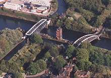
The structure is adjacent to, and upstream of, the Barton Road Swing Bridge. Both bridges are operated from a brick control tower on an island in the centre of the ship canal. When in the open position, the aqueduct and road bridge line up along the length of the island, allowing ships to traverse each side.[6][10] To avoid the risk of collision, the aqueduct is opened half an hour before traffic on the Manchester Ship Canal is scheduled to pass.[11]
Turning mechanism
The turning mechanism built into the central island consists of a 27-foot (8.2 m) race plate embedded in granite blocks. Sixty-four tapered cast iron rollers sat on top of the race plate, held in position by a spider ring. On top of that an upper race plate supports the aqueduct and its circular gear rack, which was powered by a hydraulic engine manufactured by Sir W. G. Armstrong Mitchell of Newcastle.
To reduce the pressure on the turning mechanism, a hydraulic press was installed in the pivot. When water was admitted to the press it took up to half the weight. So successful was this system of hydraulic assistance that Leader Williams retrofitted it to several road swing bridges being built over the Ship Canal including the ones at Stockton Heath and Knutsford Road in Warrington.
The weight of the structure meant that the design was pushing the limits of the possible. This became clear when the sixty-four 35.5cm (14 inches) mean diameter hollow cast-iron rollers started to deform. By 1927 the structure had dropped by 8.89cm (3 1/2-inches). In 1928 the iron rollers were replaced with steel and since then the bridge has dropped by only 2.4mm (3/32-inch). Once the iron rollers were replaced the hydraulic press assistance was dispensed with.[12]
Hydraulic power was originally supplied by steam from two Lancashire boilers housed in a pumping station on the Eccles bank of the ship canal;[13] a service culvert beneath the bed of the canal conveyed the water under pressure to the control tower on the island.[14] In 1939 the original hydraulic engines were replaced by a pair of radial three-cylinder engines manufactured by the Hydraulic Engineering Company of Chester, and the following year a power house was built on the island to house two electrically driven pumps. The old steam pumping station was demolished after the Second World War.[9]
See also
References
Notes
- ↑ "Northwest firsts – facts and figures", Industrial Powerhouse, 2009, retrieved 5 September 2010
- 1 2 3 "Barton Swing Aqueduct", Images of England, archived from the original on 29 September 2008, retrieved 20 January 2008
- 1 2 3 "Facts and Figures", Manchester Ship Canal, archived from the original on 5 November 2007, retrieved 1 October 2007
- ↑ Atkinson (2002), p. 36
- 1 2 Nevell (1997), p. 135
- 1 2 Ryall (2000), p. 686
- ↑ The Manchester Ship Canal: a brief history. (PDF), Clydeport.co.uk, archived from the original (PDF) on 5 September 2008, retrieved 20 January 2008
- ↑ Atkinson (2002), pp. 27–28
- 1 2 Atkinson (2002), p. 45
- ↑ "Barton Swing Aqueduct", The Tourist Engineer, 15 June 2008, archived from the original on 17 September 2008, retrieved 20 January 2010
- ↑ Fisher (2013), p. 236
- ↑ "The register (2016)".
- ↑ Atkinson (2002), pp. 41–42.
- ↑ Atkinson (2002), p. 44
Bibliography
- Atkinson, Glen (2002), Barton's Bridges, Neil Richardson, ISBN 978-1-85216-146-0
- Fisher, Stuart (2013), The Canals of Britain: A Comprehensive Guide, A&C Black, ISBN 978-1-4081-0524-5
- Nevell, Mike (1997), The Archaeology of Trafford, Trafford Metropolitan Borough with University of Manchester Archaeological Unit, ISBN 978-1-870695-25-1
- Ryall, M. J. (2000), The Manual of Bridge Engineering, Thomas Telford, ISBN 978-0-7277-2774-9
Further reading
- Cossons, Neil (1987), The BP Book of Industrial Archaeology, David & Charles
- Fletcher, John C. (1992), The History and Operation of Barton Swing Aqueduct, John & Margaret Fletcher, ISBN 978-0-9519058-0-7
External links
| Wikimedia Commons has media related to Barton Swing Aqueduct. |
- Videos of the aqueduct in motion
- Video of narrowboat crossing the aqueduct
- Barton Swing Aqueduct
- Bridgewater Canal
Buildings and structures in the City of Salford, England | ||
|---|---|---|
Italics denote building under construction | ||
| Highrises (over 50 metres) |     | |
| Notable lowrises |
| |
| Places of Worship | ||
| Transportation | ||
| Entertainment | ||
| Sports venues | ||
| Memorials | ||
| Bridges | ||