Cache memory
In data processing systems (computers), a cache memory or memory cache (or sometimes also CPU cache (*)) is a fast and relatively small memory, not visible to the software, that is completely handled by the hardware, that stores the most recently used (MRU) main memory (MM) (or working memory) data.
The function of the cache memory is to speed up the MM data access (performance increasing) and most important, in multiprocessor systems with shared memory, to reduce the system bus and MM traffic that is one of the major bottleneck of these systems.
Cache memory makes use of the fast technology SRAM (static random-access memory cells), against a slower MM DRAM (dynamic random-access memory), connected directly to the processor(s).
The term "cache" is derived from the French (pronounced /ˈkæʃ/cash/ (deprecated template)) and means "hidden".
This term has many meanings depending on the context. Examples are: disk cache, TLB (translation lookaside buffer) (Page Table cache), branch prediction cache, branch history table, Branch Address Cache, trace cache, that are physical memories. Others are handled by the software, to store temporary data in reserved MM space (again disk cache (page cache), system cache, application cache, database cache, web cache, DNS cache, browser cache, router cache, etc.). Some of these last ones are actually only "buffers" , that is a non-associative memory with sequential access (strings of data) against the random accesses through an associative "memory-to-cache" address of a classic cache.
The term "cache memory" or "memory cache" or shortly "cache" without any specification, usually is referred to a
"hidden memory that stores a subset of main memory content "
and specifically the "Instructions" of a program and the related "Data" that must be processed.
- (*) Note – "CPU cache" is unusual term and rarely or for nothing used both in literature than in industrial environment between the experts in this field. For instance, in the US patents documents relating to the cache, the term "CPU cache" is used in less of 2% of the documents against to the "Cache Memory" (83%) and the "Memory Cache" (15%) .
Cache general definition
The Cache is a memory that stores temporary data, in "silent mode" to upper level of utilization,
for a quick reusing.
Functional principles of the cache memory

1. In MM read operation, the cache controller first of all checks if the data is stored in cache.
2. In case of match (Hit - cache hit ) the data is fastly and directly supplied from the cache
to the processor without involving the MM.
3. Else (Miss - cache miss ) the data is read from MM.
Cache Memory operation is based on two major "principles of locality" (see Locality of reference):
- - Temporal locality
- - Spatial locality'
- Temporal locality
- - Data that have been used recently, have high likelihood of being used again
- A cache stores only a subset of MM data – the most recent-used MRU. Data read from MM are temporary stored in cache. If the processor requires the same data, this is supplied by the cache. The cache is effective because short instruction loops and routines are a common program structure and generally several operations are performed on the same data values and variables.
- Spatial locality
- - If a data is referenced, is very likely that nearby data will be accessed soon.
- Instructions and data are transferred from MM to the cache in fixed blocks (cache block), known as cache lines. Cache line size is in the range of 4 to 512 bytes[1] so that more than one processing data (4/8 bytes) is stored in each cache entry. After a first MM access, all cache line data are available in cache.
- Most programs are highly sequential. Next instruction usually comes from the next memory location. Data is usually structured and data in these structures normally are stored in contiguous memory locations (data strings, arrays, etc.).
- Large lines size increase the spatial locality but increase also the number of invalidated data in case of line replacement (see Replacement policy).
(Note – for brevity, the term "data" often will be used instead of "cache line" or "cache block")
Cache efficiency
Cache efficiency is measured in terms of "Hit Rate". Hit Rate represents the percentage of Hits (data found in cache) compared to the total number of cache accesses. The opposite of "Hit" is called "Miss"
The cache efficiency depends by several elements: cache size, line size, type and cache architecture (see below) and applications. A good figure of the cache efficiency, for business applications, may be in the range of 80-95 % of hit.[2]
Cache organization and structure
There are three basic structures and two (plus one) types of caches:
- Fully Associative cache
- Direct Mapped cache
- Set Associative cache
Types:
- Instruction cache
- Data cache
- Stack cache
- – a special "Data cache" called Stack cache (see below Stack cache)
Fully associative cache

Any memory block can be stored in any cache location. It is called "fully associative" because each data stored in cache is associated to its full address.
The cache is divided into two arrays: Directory and Data. The Directory is also divide in two fields: data attribute bits or State and data address ADD (address of memory block).
Data attribute includes the Valid bit and several other flags as Modified bit (M), Shared bit (S) and others (see below Cache states). In addition can include the "protection bits" like "Supervisor/User" and "Write protection".
In fully associative cache the full address of the block is stored. When a data is read from cache, all addresses stored into "Directory" field are simultaneously compared with the MM address block of the required data. If match is found with valid data (hit), the correspondent data is read from the cache. In case of miss, the data block is read from MM. The data read from MM is also then stored in cache that will replace (overwrite) the selected cache line according to Replacement policy.
Fully Associative cache has high efficiency. The data can be stored in any entry, but it is expensive in term of circuits. It requires independent simultaneous ways of access and a comparator for each cache entry. Therefore, usually, the size of this type of cache is very small and used only for specific cases ( e.g. TLB). Generally this cache is never used as cache memory, but instead the direct-mapped and set-associative are used.
Direct mapped cache
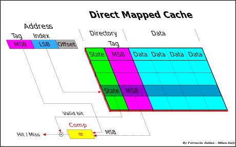
In direct mapped (or single set-associative cache) any memory block can be stored in one specific cache entry only. The entry where to store the block is direct derived from the memory address (so that the name "Direct-Mapped").

Cache size is smaller than the MM, therefore the memory address must be reduced to match the cache space. All memory data must take place in a lower space, but of course, not at the same time. Many algorithms, called hash coding or (hashing), are used to do this. The common solution (*) to obtain the cache address is to use directly a part of the memory address, and more precisely, the field called Index, that is, excluding the offset, the Least Significant Bits (LSB) of the address (see fig. Cache addressing). The offset (line offset) is the address field used for the internal cache line addressing at byte-level. For instance having a 32-bit memory addressing (4 GB space), and a 4 MB cache size with 256 B line size, the less significant bits (8-21), the Index, are used to select the entry cache. This linear addressing solution, in Demand-paging Virtual memory (see also below Virtual memory), allows to store a full Memory page in cache.
- (*) Note – Another possible hash coding algorithm, but used same time only for TLB, is the "bit XORing" of the address. The address reduction is obtained making an XOR (exclusive OR) between pairs of bits. This method generates a pseudo-random addressing.
All data having the same Index, called synonyms, are stored in the same entry, so that only one synonym at a time can take place in cache (synonym conflict). Synonyms differ each other for the MSB (Most Significant Bits) address field.
To distinguish different synonyms, the MSB (named address Tag) is stored in cache directory (in previous example bits (22-31). When a data is read from the cache, the MSB of the directory of the cache is compared with the MSB of the memory address of the data to be read. As well as in Fully Associative, in case of hit, the data is read from cache, else miss, from MM.
The distance between two synonyms, in term of address, is a multiple of the cache size. Synonym conflict decrease with increasing the cache size because the distance between synonyms increase.
In this type of cache only a cache line at a time is selected and therefore only a comparator is needed.
To minimize synonym problem a Set Associative cache is used.
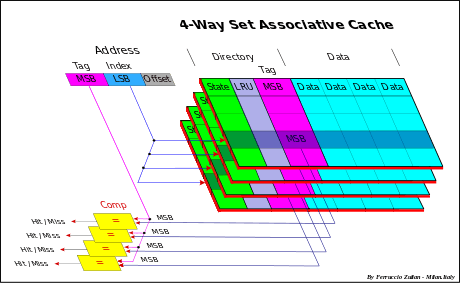
Set associative cache
Set associative cache (or multi-way-direct-mapped) is a combination of two previous approaches and it is used to reduce synonyms conflict.
This cache is composed by a set of identical Direct Mapped cache, addressed in the same identical way, so that for each entry a set of alternative cache line are available to store more than one synonym. Synonyms can be stored in any set of the direct mapped of the selected entries, depending on the (Replacement policy) algorithm used (usually LRU).
Usually the number of ways is in the range of 2-8/16 or more, up to 48 (AMD Athlon[3]) and 128 (IBM POWER3[4]), depending of the type of the cache (Instruction/Data).
In a Set Associative cache there is an address comparator for each set.
- Note: a Direct Mapped can be see as a Set Associative cache with only one way, and a Fully Associative cache with n-entries as a n-way Set Associative cache with just one entry.
Depending on the "Replacement policy" adopted, the Directory may or not contain also the Replacement bits to select the cache line candidate to be replaced.
Replacement policy
(cache line deallocation)
When there are more than one available entry to store a data, as in case of Fully Associative and Set Associative cache, the entry to be replaced is selected by the "Replacement policy" adopted.
There are different policies.[5][6]
The main are:
- LRU – Least Recently Used
- FIFO – First-In First-Out
- LFU – Least Frequently Used
- Round-robin
- Random
- – LRU
- – Commonly used for Set Associative cache
- – An age counter (replacement index) is associated to each entry of each "set". The max capacity of this counter is equal to the number of the "set". The cache line of an entry that has the highest value is the one that will be replaced by the new cache line. Each time a cache line is accessed its counter is set to zero, while the other counters of the other cache lines of the same entry with a lower value of the accessed line, are increased by 1. For instance with 4-way Set Associative and therefore with two bit-counter, with counters having the value 0-3-2-1 (set from 1 to 4) the replacement order will be 4th-1st-2nd-3th. The highest value (3) is the oldest and the lowest value (0) is the most recent (or could also be vice versa in an alternative implementation).
- - if the set 3 is accessed, the final result will be: counters value 1-3-0-2, replacement order 3th-1st-4th-2nd . The Set 3 is moved to the last position.
- - In case of a line replacement, the line repleced will be the set 2 and the counters become 2-0-1-3, replacement order 2nd-4th-3th-1st.
- – FIFO
- – Used in Set Associative cache
- – The same algorithm of LRU but with the difference that the counters are updated only when a cache line is replaced. The cache line with the highest value is replaced and its counter is set to zero while all the other counters are increased by 1.
- – LFU
- – More efficient algorithm but the highest cost. Generally not used
- – Round-robin
- – Used in Full Associative cache
- – A pointer selects the cache line that to be replaced. This pointer is increased by 1 every cache line replacement. This is done in cyclical way. Only a pointer is necessary.
- – Simple and cheap to implement
- – Random
- – Used in Full Associative cache
- – Round-robin updated every clock/access instead of every replacement.
- – Simple and cheap to implement
Types of cache
Instruction and data cache
Two types of information are stored in MM, Instructions (also called code) and Data (as operands).
- "Unified " cache stores both.
- In "Separated " cache, Instructions and Data are stored in dedicated caches. These caches are shortly called "I-Cache" for Instruction cache and "D-Cache" for Data cache.
There are three advantages in separated caches:
- Interference reduction between two different structures of data.
- - More sequential the Instructions, more random the Data. Moreover, this approach allows different cache implementation. Usually from 2 to 4/8-way Associative cache for Instructions, from 4 to 16-way or more (128) for Data cache.[4]
- Allows "Harvard architecture " implementation. This type of architecture increases the parallelism execution of the processor because allows parallel instructions accesses (prefetching) with the access and execution of the previous data related to the previous instructions (independent parallel access ways).
- No interference, in multiprocessor systems, between snoopy activity and processor activity on the I-Cache. Snoopy activity is generally made only in D-Cache (see below Write policy and Snoopy and processor activity interference).
Non-blocking cache
Most caches can only handle one outstanding request at a time. If a request is made to the cache and there is a miss, the cache must wait the data from the memory, and until then, it is "blocked". A non-blocking (or lock-free) cache has the ability to work on other requests while waiting for memory to supply any misses.
Write policy
The cache's write policy determines how it handles writes to memory locations that are currently being held in cache.
Generally only the Data Cache is involved, because usually the instructions are not self-modifying, and in case of code self-modifying, the software force to store this code only in MM without to involve the cache (see for instance AMD64 Self-Modifying Code[7]).
There are two basic policies types:
- Write Through
- Write-Back (or Copy Back)
Write through
- Data is written at the same time both in cache and in MM, or in cache and then in memory (from which the name).
Write-back (or copy back)
- Data is updated only in cache. The data is "written back" in MM when needed, for instance in case of cache line replacement (overwrite) or when required by other caches. This reduce bus and memory traffic because next cache line updating are taken only in cache without involving the memory. The bit "D" or "M" – (Dirty or Modified) is set on in cache Directory (see below Cache states).
In case of miss on write there are two different solutions:
Write allocate
- Write allocate on miss called also Fetch-on-write or RWITM (Read With Intent To Modify) or Read for Write
- On a write miss, the cache line is first read from Main Memory or from a cache in case of Cache Intervention, then the data is written in cache with the new data – cache line updating – (cache line partial write: byte, halfword, word or doubleword – 8, 16, 32 or 64 bit, according to intrinsic parallelism of the processing unit
Write no-allocate
( or no-Write allocate)
The data is directly written in MM bypassing the cache
- Write allocate usually is associated to write-back. Write no-allocate may be or not associate to write-through.
Cache levels
In a system more than one cache can be used. The caches are organized in hierarchy levels. Up to 4 level, L1 to L4 or more are possible.[8][9]
Larger cache have better hit rates but a longer latency. Multi-level cache allows fast access with high hit-rate.
Multi-level cache generally operates by checking the smallest cache first, of lower level, the Level 1 (L1); if hits, the processor proceeds at high speed. If the smaller cache misses, the next larger cache (L2) is checked, and so on for the highest level cache.
Technology improving allows enough space to store a small L1 cache inside the processor chip. An internal cache is faster than an external cache but has lower Hit Rate due to smaller size, typically in the ranges from 8 KB to 64 KB. To increase the global cache size and so the Hit rate, a greater L2 cache closely coupled to the processor is used. Typically L2 size is in the range from 64 KB to 8 MB. L2 can be external or internal to the processor chip or package. In this last case a larger external L3 cache (4-256MB) can be also used. In multi-core systems L3 can be implemented in a MCM (Multi-Chip Module) (e.g. POWER4).

Usually L1 is a Set Associative separated, Instruction and Data cache. L2 cache can be an unified or separated cache as well as can be a Direct Mapped or Set Associative cache. The same for L3 cache.
Multi-level cache hierarchy function
- - L1 --> Inside the processor chip. Fast access.
- - L2 --> To increase the global size and for data coherency.
- – Snoopy for multiprocessor bus-based, shared for multi-core.
- – Can be external or internal to the processor chip.
- – Range 64 KB – 8 MB (16 MB IBM RS64-IV).[1]
- - L3 --> To increase the global size. Used also as Victim cache of the L2 (see #Inclusive and exclusive cache). Architectures that use L3 in this way are POWER5 and AMD.
- and for snoopy in SMP System.
- – Range 4 MB – 128 MB[1][10] L3 is used if L2 is internal to the chip or the die.
- - L4 --> Remote cache for cc-NUMA Clastering System.
Note: The cache line size of the upper level cache can be equal or greater of the lower level cache.
Inclusive and exclusive cache
Cache can be inclusive or exclusive.
- Inclusive means that the content of the L1 cache is also included in the L2 cache, that is L1 is a subset of L2.
- L2 cache stores a copy of L1 plus the L1 evicted data (victim data due to a line replacement).
- L2 inclusive implies that L1 must be a write through versus L2.
- The effective cache size of the system is the size of L2 only.
- Same relation between L3 inclusive and L2 cache, if L3 is used.
- Operations
- – Miss in L1 and Hit in L2
- – The cache line of L2 is copied in L1.
- – Miss in L1 and in L2
- – The data read from memory is stored both in L1 and L2, replacing in L1 the same line replaced in L2, if L1 has a copy of its, otherwise the cache line to be replaced in L1 will be chosen depending on the replacement policy used.
- – When a cache line in L2 is replaced, due a miss conflict in L2, also the eventual copy in L1 must be evicted to maintain the inclusivity.
- – Miss in L1 and Hit in L2
- Exclusive (or not inclusive) means that a data can be stored just in one cache only.
- L2 cache contains only copy-back cache line that are ejected from L1 due to conflict misses (victim lines). This type of cache therefore is called also "Victim cache".
(Note – The size of the global cache is equal to L1 plus L2 size).
- Same relation between L3 exclusive and L2 cache, if L3 is used.
- L2 cache contains only copy-back cache line that are ejected from L1 due to conflict misses (victim lines). This type of cache therefore is called also "Victim cache".
- Operations
- – Miss in L1 and Hit in L2
- – Cache lines of L1 and L2 are switched between them, that is the cache line of L1 is stored in L2 and the cache line of L2 in L1.
- – Miss in L1 and in L2
- – The data read from memory is stored directly in L1 and the replaced line (victim data) of L1 is transferred in L2 replacing another cache line depending on the replacement policy used.
- Inclusivity vs Exclusivity
- Inclusivity is preferable in multiprocessor/multi-core systems bus-based environment for data coherency, otherwise the coherency control must be done in all caches (see below Snoopy and processor activity interference). The inclusiveness simplifies cache coherence.
- The downside of the inclusive cache is that the L2 cache contains redundant data, this means a global size reduction. This is effectively only if the L1 and L2 cache size are comparable. Often the L2 size is a order of magnitude of L1, so that the penalty of hit rate due to the global size reduction may be very low (few percents), considering also that in the range of 80-95 % of hit-rate, increasing the size, the gain of hit-rate tends quickly to being flat.[2]
- The same considerations can be done for L3 versus L2 cache (e.g. Shanghai (AMD) vs Nehalem-EP (Intel)[12])
Shared cache
Processors can share a common cache. Shared caches generally are used for data coherency in multi-core systems and for cost reduction (see below Shared cache – coherency protocol).
Multi-bank and multi-ported cache
Superscalar processor architecture allows simultaneous parallel instructions execution (taking advantage of the intrinsic parallelism in the instruction stream/multithread ). In these kind of processors there are several function units of the same type, along with additional circuitry to dispatch instructions to the units. Most superscalar designs include more than one arithmetic-logic unit. For instance in IBM POWER3[13] up to eight instructions, two floating point, two load/store, three fixed point (two single-cycle integer, a multi-cycle integer) and a branch can be in execution in each cycle. Ready instructions are issued out of order from the issue queues, allowing instructions of different types, as well as of the same type, to execute out of order by using the Register renaming technique for synchronization and reorder of the results.
Parallel instructions execution requires multiple simultaneous L1 D-cache accesses. Conflicts occur when two or more requests need to access to the same cache bank simultaneously. This conflict can be partially eliminated by using using multi-bank and/or multi-ported cache techniques.[14][15][16]
There are several solutions[17][18]
- Multi-bank cache
- Multi-ported cache
- Multiple cache copies
- Virtual multi-porting cache
- Hybrid solution
Multi-bank cache
L1 D-cache is divided in multiple independently-addressed banks.
There are two approaches:
- Linear addressing
- Cache interleaving
Linear addressing
The banks are accessed in parallel through a crossbar. The addressing is linear, that is the next address of the last address of a bank is the first address of the next bank. The banks are selected in sequence by using the most significant bits (MSB) of the address Index (for instance, with 8 banks, the three bits 21-19 of above example in Cache addressing). Multiple banks can support multiple requests per cycle when they do not map to the same bank.
Multi-bank approach may be efficient for applications that lack of data locality (statistically independent data), but for applications with good spatial locality, such consecutive reference, simultaneous multiple accesses are not allowed due to a bank conflict (bank collision).
Cache interleaving
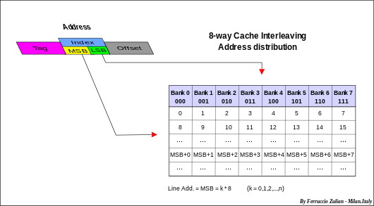
Consecutive cache line are placed in consecutive banks. The cache line addressing is interleaved (horizontally distributed) across the banks as shown in fig. aside. The banks are selected by using the low-order bits of the Index of the address (for instance, with 8-way interleaving, the three bits 10-8 of above example in Cache addressing).
The common number of banks are two, four or eight (e. g. IBM POWER3[19]), named two-way, four-way or eight-way interleaving respectively.
Cache interleaving gives advantages specially in multiple data strings operations. For instance, suppose a two-way interleaved cache with address pairs in Bank 0 and address odd in Bank 1 and two programs (treads) that operate on two independent strings. The fist program can access to the Bank 0 while the second to the Bank 1. Next access, the first program can access to the Bank 1 while the second to the Bank 0, and so on alternatively. In case of bank collision, that is simultaneous access to the same bank, a program at the beginning must wait just for a step (the first time only), then can start. Like a linear addressing also in multiple simultaneous random accesses there are advantages depending on the banks number. Conflict probability decreases increasing the banks number.
Example of interleaving: IBM POWER3's L1 data cache[20] an eight-way interleaved cache, is capable of two loads, one store, and one cache line reload per cycle.
Multi-ported cache
(or multi-port cache or true multi-porting or ideal multi-porting )
Multiple ports allow multiple parallel accesses to the cache, in the same clock cycle, that operate independently from each other.[1][21]
Multi-ported caches offer the highest possible access rate per cycle but are complex, and thus slow and costly. Ideal multi-porting implies non-standard cache cell structure. While a regular single-ported static memory cell requires 6 field-effect transistors to be built upon, a dual-ported static memory cell needs additional 2 transistors.
Therefore, this solution can only be used for few ports, usually two ports read and one port write (e.g. POWER4).
Multiple cache copies
(mirroring or cloning)
Cache with "n" identical copies (clones) with independent simultaneous addressing. Drawback: cache replicated without benefit to storage space. Moreover, store requests are sent simultaneously to all cache copies, thus no other cache request can be sent in parallel. Since about 30% of memory accesses are stored[22] this solution is severely limited.
Virtual multi-porting cache
(time division multiplexing)
Time division multiplexing is a technique which may be also referenced as cache over-clocking. Cache memory running at 2x (3x, 4x) processor clock speed so that the cache can be accessed two (three, four) time per clock.
Hybrid solution
Combination of cache interleaved with multi-port. Multiple banks interleaved allow parallel access at low cost while multiple ports help removing bank conflicts.
Cache coherency
In systems as SMP – Symmetric Multiprocessor System, multi-core and NUMA system, where a dedicated cache for each processor, core or node is used, a consistency problem may occur when same data is stored in more than one cache. This problem arises when data is modified in one cache. This problem can be solved in two ways:
- 1. Invalidate all the copies on other caches (broadcast-invalidate)
- 2. Update all the copies on other caches (write-broadcasting), while the memory may be updated (write through) or not updated (write-back).
Note: data coherency generally regards only the data (as operands) and not the instructions (see Self-Modifying Code).
The schemes can be classified based on:
– Snoopy scheme vs Directory scheme and vs Shared caches
– Write through vs Write-back (ownership-based) protocol
– Update vs Invalidation protocol
– Intervention vs not Intervention
– Dirty-sharing vs not-dirty-sharing protocol (MOESI vs MESI)
Three approaches are adopted to maintain the coherency of data.
- Bus watching or Snooping – generally used for bus-based SMP – Symmetric Multiprocessor System/multi-core systems
- Directory-based – Message-passing – may be used in all systems but typically in NUMA system and in large multi-core systems
- Shared cache – generally used in multi-core systems
Snoopy coherency protocol
Protocol used in bus-based system like a SMP systems
SMP – symmetric multiprocessor systems
Systems operating under a single OS (Operating System) with two or more homogeneous processors and
with a centralized shared Main Memory
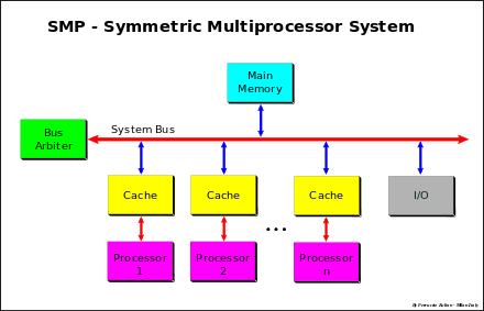
Each processor have a its own cache that acts as a bridge between processor and Main Memory. The connection is made using a System Bus or a crossbar[23] (xbar) or a mix of two previously approach, bus for address and crossbar for Data (Data crossbar).[24][25][26]
The bottleneck of these systems is the traffic and the Memory bandwidth. Bandwidth can be increasing by using large data bus path, data crossbar, memory interleaving (multi-bank parallel access) and out of order data transaction. The traffic can reduced by using a cache that acts as a "filter" versus the shared memory, that is the cache is an essential element for shared-memory in SMP systems.
In multiprocessor systems with separate caches that share a common memory, a same datum can be stored in more than one cache. A data consistency problem may occur when a data is modified in one cache only.
The protocols to maintain the coherency for multiple processors are called cache-coherency protocols.
Usually in SMP the coherency is based on the "Bus watching" or "Snoopy" (from the dog Snoopy ) approach.
In a snooping system, all the caches monitor (or snoop) the bus transactions to intercept the data and determine if they have a copy on its cache.
Various cache-coherency protocols are used to maintain data coherency between caches.[27]
These protocols are generally classified based only on the cache states (from 3 to 5 and 7 or more) and the transactions between them, but this could create some confusion.
This definition is incomplete because it lacks important and essential information as the actions that these produce. These actions can be invoked from processor or bus (e.g. intervention, invalidation, broadcasting, updating, etc.). The type of actions are implementation depending. Protocols having the same states and the same transaction rules may be different, for instance protocol MESI with shared-intervention on unmodified data and MESI without intervention (see below). Protocols with different states may be practically the same protocol, for instance the 4-state MESI Illinois and 5-state MERSI (R-MESI) IBM / MESIF-Intel protocols are only a different implementation of the same functionality (see below).
The most common and popular protocols are considered the 4-state cache known as acronyms MESI and 5-state MOESI, this just only for easy pronunciation, terms derived from the name of the states used. Other protocols use the same states or un subset of these but with different implementations and often with different but equivalent terminology. With the term MESI or MOESI or a subset of these, generally it is referred to a class of protocols instead of a specific protocol.
Cache states
The states MESI and MOESI are often and more commonly called with different names.
- M=Modified or D=Dirty or DE=Dirty-Exclusive or EM=Exclusive Modified
- – modified in one cache only – write-back required at replacement.
- – data is stored only in one cache but the data in memory is not updated (invalid, not clean).
- O=Owner or SD=Shared Dirty or SM=Shared Modified or T=Tagged
- – modified, potentially shared, owned, write-back required at replacement.
- – data may be stored in more than a cache but the data in memory is not updated (invalid, not clean). Only one cache is the "owner", other caches are set "Valid" (S/V/SC). On bus read request, the data is supplied by the "owner" instead of the memory.
- E=Exclusive or R=Reserved or VE=Valid-Exclusive or EC=Exclusive Clean or Me=Exclusive
- – clean, in one cache only.
- – Data is stored only in one cache and clean in memory.
- S=Shared or V=Valid or SC=Shared Clean
- – shared or valid
- – Data potentially shared with other caches. The data can be clean or dirty. The term "clean" in SC is misleading because can be also dirty (see Dragon protocol).
- I=Invalid.
- – Cache line invalid. If the cache line is not present (no tag matching) it is considered equivalent to invalid, therefore invalid data means data present but invalid or not present in cache.
Special states:
- F=Forward or R=Recent
- – Additional states of MESI protocol
- – Last data read. It is a special "Valid" state that is the "Owner" for non modified shared data, used in some extended MESI protocols (MERSI or R-MESI IBM,[28][29] MESIF – Intel[30][31]). The R/F state is used to allow "intervention" when the value is clean but shared among many caches. This cache is responsible for intervention (shared intervention ). On bus read request, the data is supplied by this cache instead of the memory. MERSI and MESIF are the same protocol with different terminology (F instead of R). Some time R is referred as "shared last " (SL).[21][32]
- Note – The state R = Recent is used not only in MERSI = R-MESI protocol but in several other protocols. This state can be used in combination with other states. For instance RT-MESI, HR-MESI, HRT-MESI, HRT-ST-MESI.[29][33][34] All protocols that use this state will be refereed as R-MESI type.
- H=Hover – H-MESI (additional state of MESI protocol)[33]
- – The Hover (H) state allows a cache line to maintain an address Tag in the directory even though the corresponding value in the cache entry is an invalid copy. If the correspondent value happens on the bus (address Tag matching) due a valid "Read" or "Write" operation, the entry is updated with a valid copy and its state is changed in S.
- – This state can be used in combination with other states. For instance HR-MESI, HT-MESI, HRT-MESI, HRT-ST-MESI.[29][33][34]
Various coherency protocols
Protocols
- SI protocol Write Through
- MSI protocol Synapse protocol[27]
- MEI protocol IBM PowerPC 750,[35] MPC7400[29]
- MES protocol Firefly protocol[27]
- MESI protocol Pentium II,[36] PowerPC, Intel Harpertown (Xeon 5400)
- MOSI protocol Berkeley protocol [27]
- MOESI protocol AMD64,[37] AMD Opteron,[23] MOESI,[38] T-MESI IBM[34]
————————————————————————————————————————
Terminology used
- Illinois protocol D-VE-S-I (= extended MESI)[27][39]
- Write-once or Write-first D-R-V-I (= MESI) [27][40][41]
- Berkeley protocol D-SD-V-I (= MOSI) [27]
- Synapse protocol D-V-I (= MSI) [27]
- Firefly protocol D-VE-S (= MES) DEC[27]
- Dragon protocol D-SD (SM ?)-SC-VE (= MOES) Xerox[27]
- Bull HN ISI protocol D-SD-R-V-I (= MOESI)[42]
- MERSI (IBM) / MESIF (Intel) protocol R=Recent – IBM PowerPC G4, MPC7400[28][29]
F=Forward – Intel[30] Intel Nehalem[12][43][44]
- HRT-ST-MESI protocol H=Hover, R=Recent,T=Tagged, ST=Shared-Tagged – IBM[33][34]
– Note: The main terminologies are SD-D-R-V-I and MOESI and so they will be used both.
————————————————————————————————————————
- POWER4 IBM protocol T-Mu-Me-M-S-SL-I ( L2 seven states)[21]
Mu=Unsolicited Modified – Modified Exclusive – (D/M) (*)
T=Tagged – Modified Owner not Exclusive (SD/O)
Me=Valid Exclusive – (R/E)
S=Shared – (V)
SL=Shared Last – Sourced local – (Shared Owner Local)
I=Invalid – (I)
(*) Special state – Asking for a reservation for load and store doubleword (for 64-bit implementations).
————————————————————————————————————————
Snoopy coherency operations
- - Bus Transactions
- - Data Characteristics
- - Cache Operations
Bus transactions
The main operations are:
- - Write Through
- - Write-Back
- – Write Allocate
- – Write-no-Allocate
- – Cache Intervention
- – Shared Intervention
- – Dirty Intervention
- - Invalidation
- - Write-broadcast
- - Intervention-broadcasting
- Write Through
- - The cache line is updated both in cache and in MM or only in MM (write no-allocate).
- - Simple to implement, high bandwidth consuming. It is better for single write.
- Write-Back
- - Data is written only in cache. Data is Write-Back to MM only when the data is replaced in cache or when required by other caches (see Write policy).
- - It Is better for multi-write on the same cache line.
- - Intermediate solution: Write Through for the first write, Write-Back for the next (Write-once and Bull HN ISI[42] protocols).
- Write Allocate
- – On miss the data is read from the "owner" or from MM, then the data is written in cache (updating-partial write) (see Write policy).
- Write-no-Allocate
- - On miss the data is written only in MM without to involve the cache, or as in Bull HN ISI protocol, in the "owner", that is in D or SD cache (owner updating), if they are, else in MM.
- - Write-no-Allocate usually is associated with Write Through.
- Cache Intervention
- (or shortly "intervention ")
- – Shared Intervention – shared-clean intervention (on unmodified data)
- – On Read Miss the data is supplied by the owner E or R/F or also S instead of the MM (see protocols Illinois , IBM R-MESI type and Intel MESIF).
- – Shared Intervention – shared-clean intervention (on unmodified data)
- – Dirty Intervention (on modified data)
- – On Read Miss the data is supplied by the M (D) or O (SD) owner or by E (R) (*) instead of MM (e.g. MOESI protocol, RT-MESI, …).
- – Dirty Intervention (on modified data)
- (*) – Not for E (R) in the original proposal MOESI protocol[38] and in some other implementations MOESI-Type.
- – "Intervention " is better compared to the "not intervention " because cache-to-cache transactions are much more faster than a MM access, and in addition it save memory bandwidth (memory traffic reduction). Extended MESI Illinois and R-MESI type / MESIF are therefore much better than the MOESI protocol (see MESI vs MOESI below)
- Invalidation
- – On Write Hit with S (V) or O (SD) (shared) state, a bus transaction is sent to invalidate all the copies on the other caches (Write-invalidate).
- Write-broadcast (Write-update)
- – On Write Hit with S (V) or O (SD) (shared) state, a write is forward to other caches to update their copies (e.g. Intel Nehalem[43] Dragon protocol, Firefly (DEC).
- – Note – The updating operation on the other caches some time is called also Snarfing. The caches snoop the bus and if there is a hit in a cache, this cache snarfs the data that transits on the bus and update its cache. Also the updating of the H in (H-MESI) state can be defined as snarfing. In the first case this happens in a write broadcast operation, on the second case both in read and write operations.
- Intervention-broadcasting
- Write invalidate vs broadcast
- – Write Invalidate is better when multiple writes, typically partial write, are done by a processor before that the cache line is read by another processor.
- – Write-broadcast (updating) is better when there is a single producer and many consumers of data, but it is worse when a cache is filled with data that will be not next read again (bus traffic increasing, cache interference increasing).
- - Invalidation is the common solution.
Data characteristics
There are three characteristics of cached data:
- - Validity
- - Exclusiveness
- - Ownership
- Validity
- – Any not invalid cache line, that is MOES / D-SD-R-V.
- Exclusiveness
- – Data valid only in one cache (data not shared) in M (D) or E (R) state, with MM not clean in case of M (D) and clean in case of E (R).
- Ownership
- – The cache that is responsible to supply the request data instead of a MM (Intervention) – Depending on the protocol, cache who must make the intervention can be S-E-M in MESI Illinois, or R/F-E-M in R-MESI type / MESIF or M (D) or O (SD) or also E (R) (*) in MOESI-type protocols, (e.g. AMD64,[38] Bull HN ISI[42] – see "Read Miss" operation below).
(*) – Implementation depending.
Note: Not to confuse the more restrictive "owner" definition in MOESI protocol with this more general definition.
Cache operations
The cache operations are:
- - Read Hit
- - Read Miss
- - Write Hit
- - Write Miss
- Read Hit
- – Data is read from cache. The state is unchanged
- – 'Warning: since this is an obvious operation, afterwards it will not be more considered, also in state transaction diagrams.
- Read Miss
- – The data read request is sent to the bus
- – There are several situations:
- Data stored only in MM
- – The data is read from MM.
- – The cache is set E (R) or S (V)
- – E (R) if a special bus line ("Shared line ") is used to detect "no data sharing ". Used in all protocols having E (R) state except for Write-Once and Bull HN ISI protocols (see "Write Hit" below).
- Data stored in MM and in one or more caches in S (V) state or in R/F in R-MESI type / MESIF protocols.
- – There are three situations:
- – Illinois protocol – a network priority is used to temporary and arbitrary assign the ownership to a S copy.
- Data is supplied by the selected cache. Requesting cache is set S (shared intervention with MM clean). - – R-MESI type / MESIF protocols – a copy is in R/F state (shared owner)
– The data is supplied by the R/F cache. Sending cache is changed in S and the requesting cache is set R/F (in read miss the "ownership" is always taken by the last requesting cache) – shared intervention. - – In all the other cases the data is supplied by the memory and the requesting cache is set S (V).
- Data stored in MM and only in one cache in E (R) state.
- – Data is supplied by a E (R) cache or by the MM, depending on the protocol.
– From E (R) in extended MESI (e.g. Illinois, Pentium (R) II [36]), R-MESI type / MESIF and from same MOESI implementation (e.g. AMD64)
– The requesting cache is set S (V), or R/F in R-MESI type / MESIF protocols and E (R) cache is changed in S (V) or in I in MEI protocol. - – In all the other cases the data is supplied by the MM.
- Data modified in one or more caches with MM not clean
- Protocol MOESI type – Data stored in M (D) or in O (SD) and the other caches in S (V)
- – Data is sent to the requesting cache from the "owner" M (D) or O (SD). The requesting cache is set S (V) while M (D) is changed in O (SD).
- – The MM is not updated.
- Protocols MESI type and MEI – Data stored in M (D) and the other caches in S (V) state
- – There are two solutions:
- – Data is sent from the M (D) cache to the requesting cache and also to MM (e.g. Illinois, Pentium (R) II [36])
- – The operation is made in two steps: the requesting transaction is stopped, the data is sent from the M (D) cache to MM then the wait transaction can proceed and the data is read from MM (e.g. MESI and MSI Synapse protocol).
- – All cache are set S (V)
- Write Hit
- – The data is written in cache
- – There are several situations:
- Cache in S (V) or R/F or O (SD) (sharing)
- – Write invalidate
- – Copy back
- – The data is written in cache and an invalidating transaction is sent to the bus to invalidate all the other caches
- – The cache is set M (D)
- – Write Through (Write-Once, Bull HN ISI)
- – Data is written in cache and in MM invalidating all the other caches. The cache is set R (E)
- – Copy back
- – Write broadcasting (e.g. Firefly, Dragon)
- - The data is written in cache and a broadcasting transaction is sent to the bus to update all the other caches having a copy
- – The cache is set M (D) if the "shared line" is off, otherwise is set O (SD). All the other copies are set S (V)
- Cache in E (R) or M (D) state (exclusiveness)
- – The write can take place locally without any other action. The state is set (or remains) M (D)
- Write Miss
- – Write Allocate
- – Read with Intent to Modified operation (RWITM)
- – Like a Read miss operation plus an invalidate command, then the cache is written (updated)
- – The requesting cache is set M (D), all the other caches are invalidated
- – Write broadcasting (e.g. Firefly, Dragon)
- – Like with a Read Miss. If "shared line" is "off" the data is written in cache and set M (D), otherwise like with a Write Hit – Write Broadcasting
- – Read with Intent to Modified operation (RWITM)
- – Write-no-Allocate
- – The data is sent to MM, or like in Bull HN ISI protocol, only to the D (M) or SD (O) cache if they are, bypassing the cache.
- – Write Allocate
Coherency protocols
- – warning – For simplicity all Read and Write "miss" state transactions that obviously came from I state (or Tag miss), in the diagrams are not depicted. They are depicted directly on the new state.
- – Note – Many of the following protocols have only historical value. At the present the main protocols used are R-MESI type / MESIF and HRT-ST-MES (MOESI type) or a subset of this.
————————————————————————————————————————
MESI protocol
States MESI = D-R-V-I
- – Use of a bus "shared line" to detect "shared" copy in the other caches
- Processor operations
- Read Miss
- There are two alternative implementations: standard MESI (not intervention) and extended MESI (with intervention)
- 1 – MESI "no Intervention" (e.g. PowerPC 604 [45])
- – If there is a M copy in a cache, the transaction is stopped and wait until the M cache updates the MM, then the transaction can continue and the data is read from MM. Both caches are set S
- – else the data is read from MM. If the "shared line" is "on" the cache is set S else E
- 2 – MESI "Intervention" from M and E (e.g. Pentium (R) II [36])
- – If there is a M or E copy (exclusiveness) in a cache, the data is supplied to the requesting cache from M or from E (Intervention). If the sending cache is M the data is also written at the same time in MM (copy back). All caches are set S
- – else the data is read from MM. If the "shared line" is "on" the cache is set S else E
- Write Hit
- – If the cache is M or E (exclusiveness), the write can take place locally without any other action
- – else the data is written in cache and an invalidating transaction is sent to the bus to invalidate all the other caches
- – The cache is set M
- Write Miss
- – RWITM operation is sent to the bus. The operation is made in two step: a "Read Miss" with "invalidate" command to invalidate all the other caches, then like with a "Write Hit" with the state M (see Cache operation-Write Miss).
- Bus transactions
- Bus Read
- – if M and "no Intervention" the data is sent to MM (Copy Back)
- – if M and "Intervention" the data is sent to requesting cache and to MM (Copy Back)
- – if E (*) and "Intervention" the data sent to requesting cache
- – The state is changed (or remains) in S
- Bus Read – (RWITM)
- – As like with "Bus read"
- – The cache is set "Invalid" (I)
- Bus Invalidate Transaction
- The cache is set "Invalid" (I)
- Operations
- – Write Allocate
- – Intervention: from M – E (*)
- – Write Invalidate
- – Copy-Back: M replacement
- (*) – extended MESI
————————————————————————————————————————
MOESI protocol
States MEOSI = D-R-SD-V-I = T-MESI IBM[34]
- – Use of bus "shared line" to detect "shared" copy on the other caches
- Processor operations
- Read Miss
- – If there is a M or O or E (*) copy in another cache the data is supplied by this cache (intervention). The requesting cache is set S , M is changed in O and E in S
- – else the data is read from MM.
- – If "shared line" is "on" the requesting cache is set S else E
- Write Hit
- – If the cache is M or E (exclusiveness), the write can take place locally without any other action
- – else O or S (sharing) an "Invalidation" transaction is sent on the bus to invalidate all the other caches.
- – The cache is set (or remains) M
- Write Miss
- – A RWITM operation is sent to the bus
- – Data is supplied from the "owner" or from MM as with Read Miss, then cache is written (updated)
- – The cache is set M and all the other caches are set I
- Bus transactions
- Bus Read
- – If the cache is M or O or E (*) the data is sent to requesting cache (intervention). If the cache is E the state is changed in S, else is set (or remains) O
- – else the state is changed or remains in S
- Bus Read – (RWITM)
- – If the cache is M or O or E (*) the data is sent to the bus (Intervention)
- – The cache is set "Invalid" (I)
- Bus Invalidate Transaction
- – The cache is set "Invalid" (I)
- Operations
- - Write Allocate
- - Intervention: from M-O-E (*)
- - Write Invalidate
- - Copy-Back: M-O replacement
- – (*) implementation depending for E
————————————————————————————————————————
Illinois protocol
States MESI = D-R-V-I[27]
- – Characteristics:
- – It is an extension of MESI protocol
- – Use of a network priority for shared intervention (intervention on shared data)
- – Differences from MESI: in addition to E and M, intervention also from S (see Read Miss – point 1)
- Operations
- - Write Allocate
- - Intervention: from M-E-S
- - Write Invalidate
- - Copy-Back: M replacement
————————————————————————————————————————
Write-once (or write-first) protocol
States D-R-V-I (MESI) [27][40][41]
- – Characteristics:
- – No use of "shared line" (protocol for standard or unmodifiable bus)
- – Write Through on first Write Hit in state V, then Copy Back
- Processor operations
- Read Miss
- – If there is a D copy in another cache, the data is supplied by this cache (intervention) and in the same time it is written also in MM (Copy-Back).
- – else the data is read from MM
- – all caches are set V
- Write Hit
- – If the cache is D or R (exclusiveness), the write can take place locally without any other action and the state is set (or remains) D
- – else V (first Write Hit) the data is written in cache and in MM (Write Through) invalidating all the other caches (Write-Invalidate). – The cache is set R
- Write Miss
- – Like a Read Miss but with "invalidate" command (RWITM) plus a Write Hit in D state (updating). The cache is set D and all the other caches are set "Invalid" (I)
- – Note – Write Through is performed only in "Write Miss". It is point out that in this case a bus transaction in any case is needed to invalidate the other caches and therefore it can be taken advantage of this fact to update also the MM. In "Write Hit" instead no more transaction is needed so a "Write Through" it would become a useless operation in case that the cache were updated again.
- Bus transactions
- Bus Read
- – If the cache is D the data is sent to requesting cache (intervention) and to MM (copy-back). The cache is set V
- – else the state is changed or remains in V
- Bus Read – (RWITM)
- – If the cache is D the data is sent to the bus (Intervention)
- – The cache is set "Invalid" (I)
- Bus Invalidate Transaction
- – The cache is set "Invalid" (I)
- Operations
- - Write Allocate
- - Intervention: from D
- - Write Through: first write hit in V state
- - Write Invalidate
- - Copy-Back: D replacement
————————————————————————————————————————
Bull HN ISI protocol
(Bull-Honeywell Italia)
States D-SD-R-V-I (MOESI)
Patented protocol (F. Zulian)[42]
- – Characteristics:
- – MOESI extension of the Write-Once protocol
- - Write-no-allocate on miss with D or SD updating
- - No use of RWITM
- - No use of "shared line"
- Processor operations
- Read Miss
- - Like with MOESI with "Shared Line" "on" and intervention only from the "owner" D or SD but not from R
- Write Hit
- - If the cache is D or R, like with MOESI, the write can take place locally without any other action. The cache is set (or remains) D
- - If SD or V (first write), like with Write-Once, the data is written in cache and in MM (Write Through) invalidating all the other caches (Write-Invalidate) – The cache is set R
- - Write Miss
- - The data is sent to the bus bypassing the cache (Write-no-allocate)
- - If there is an "owner" copy D or SD, the "owner" is updated (see Write-no-Allocate – owner updating) while the other caches are invalidated. The "owner" is set (or remains) D. The memory remains "dirty"
- - else the data is sent to MM invalidating all the other caches (Write-Invalidate)
- - Write Miss
- Bus transactions
- Bus Read
- - Like with MOESI with intervention only from "owner" D or SD
- Bus Read (Write Update / Write Invalidate)
- - If the cache is D or SD, the cache is updated, else is set "Invalid" (I)
- Operations
- - Write-no-allocate: on miss
- - Write update: on miss
- - Write Through: for the first write, then copy back
- - Write Update / Write Invalidate
- - Intervention: from SD-D
- - Copy-Back: D replacement or SD replacement with invalidate
- Obs. - This is the only protocol that has O-E (SD-R) transactions, but the only one that does not have M-I (D-I) transactions
————————————————————————————————————————
Synapse protocol
States D-V-I (MSI)[27]
- - Characteristics:
- - The characteristic of this protocol is ti have a single-bit tag with each cache line in MM, indicating that a cache have the line in D state.
- - This bit prevents a possible race condition if the D cache does not respond quickly enough to inhibit the MM from responding before being updating.
- - The data comes always from MM
- - No use of "shared line"
- - The characteristic of this protocol is ti have a single-bit tag with each cache line in MM, indicating that a cache have the line in D state.
- Processor operations
- Read Miss
- - If there is a D copy in another cache, the read transaction is rejected (no acknowledgement). The D copy is written back to MM and changes its state in V, then the requesting cache resends a new read transaction and the data is read from MM.
- - else the data is read from MM.
- - The cache is set V
- Write Hit
- - If the cache is D , the write can take place locally without any other action.
- - else V, like with Read Miss does, including a data transfer from memory with in addition an invalidate command (RWITM). This is done only to invalidate the other V copies because this protocol does not support an invalidation transaction.
- - The cache is set D. All the other caches copy are set "Invalid" (I)
- Write Miss (RWITM)
- - Like with Read Miss, but with invalidate command. The cache line comes from MM, then the cache is written (updated). The cache is set D. All the other caches are set "Invalid" (I).
- Bus transactions
- Bus Read
- - If the cache is D, the data is sent to MM (Copy Back). The cache is set V
- - else the state remains in V
- Bus Read (RWITM)
- - If the cache is D the data is sent to MM (Copy Back)
- - The cache (D or V) is set "Invalid" (I)
- Operations
- - Write Allocate
- - Intervention: no intervention
- - Write Invalidate: (RWITM)
- - No Invalidate transaction
- - Copy-Back: D replacement
————————————————————————————————————————
Berkeley protocol
States D-SD-V-I (MOSI)[27]
- - Characteristics:
- - As with MOESI without E state
- - No use of "shared line"
- Processor operations
- Read Miss
- - The data is supplied by the "owner", that is from D or from SD else from MM. D is changed in SD
- - The cache is set V
- Write Hit
- - If the cache is D (exclusiveness), the write can take place locally without any other action
- - else (SD or V), an "Invalidation" transaction is sent on the bus to invalidate the other caches.
- - The cache is set (or remains) D
- Write Miss
- - RWITM operation is sent to the bus
- - Like with Read Miss, the data comes from the "owner", D or SD or from MM, then the cache is updated
- - The cache is set D. all the other caches are set I
- Bus transactions
- Bus Read
- - If the cache is D or SD the data is sent to requesting cache (intervention). The cache is set (or remains) in SD
- - else the cache remains in V
- Bus Read – (RWITM)
- - If the cache is D or SD the data is sent to the bus (Intervention)
- - The cache is set "Invalid" (I)
- Bus Invalidate Transaction
- - The cache is set "Invalid" (I)
- Operations
- - Write Allocate
- - Intervention: from D-SD
- - Write Invalidate
- - Copy-Back: D-SD replacement
————————————————————————————————————————
Firefly (DEC) protocol
States D-VE-S (MES)[27]
- - Characteristics:
- - No "Invalid" state
- - "Write-broadcasting"+"Write Through"
- - Use of "shared line"
- - "Write-broadcasting" avoid the necessity of "Invalid" state
- - Simultaneous intervention from all caches (shared and dirty intervention – on not modified that modified data)
- - This protocol requires a synchronous bus
- Processor operations
- Read Miss
- - Any other cache is the "owner", that is all the other caches with a copy supplied simultaneously the date on the bus (simultaneous intervention – the bus timing is fixed so that they all respond in the same cycle), otherwise the data is supplied from MM.
- - If there is a cache D, the data is sent simultaneously also to MM (Copy Back)
- - If there are copies in the other caches, the "Shared line" is set "on"
- - If "Shared line" is "on" all the caches are set S else the requesting cache is set VE.
- Write Hit
- - If the cache is D or VE (exclusiveness), the write can take place locally without any other action and the cache is set D
- - else S, a "Write-broadcasting" is sent to the bus to update all the other caches and the MM (Write Through)
- - If there is a copy in another cache, the "Shared line" is set "on". If "Shared line" is set "off" the cache is set VE else all caches are set S
- Write Miss
- - The operation is made in two steps. Read Miss then Write Hit.
- - If the data comes from a cache (Shared Line "on") a "Write-broadcasting" is sent to the bus to update all the other caches and the MM (Write Through). All the caches are set S
- - else the cache is set D
- Bus transactions
- Bus Read
- - If hit (D or VE or S) the data is sent to the bus (intervention) and in case of D the data is written also in MM. The cache is set S
- Bus Read
- - If hit (D or VE or S) the data is sent to the bus (Intervention).
- - All the caches are set S
- Write Broadcasting
- - The cache is updated with new data. The state remains S
- Operations
- - Write Allocate
- - Intervention: from D-VE-S (from all "valid" caches)
- - Write-broadcasting – Write through
- - Copy-Back: D replacement and on any transaction with a cache D
————————————————————————————————————————
Dragon (Xerox) protocol
States D-SD-VE-SC (MOES)[27]
Note – the state SC, despite of the term "clean", can be "clean" or "dirty" as the S state of the other protocols. SC and S are equivalents
- - Characteristics:
- - No "Invalid" state
- - "Write-broadcasting" (no "Write Through")
- - Use of "shared line"
- - "Write-broadcasting" avoid the necessity of "Invalid" state
- Processor operations
- Read Miss
- - The data is supplied by the "owner", that is from D or from SD else from MM. D is changed in SD
- - If "shared line" is "on" the cache is set SC else VE
- Write Hit
- - If the cache is D or VE (exclusiveness), the write can take place locally without any other action. The cache is set (or remains) D
- - else SD or SC (sharing) the data is written in cache and a "Write-broadcasting" is sent to the bus to update all the other caches – The MM is not updated (no Write through)
- - If there is a copy in another cache, the "Shared line" is set "on"
- - If the "Shared Line" is "on" the cache is set SD, else D. All the other caches possible copy are set SC
- Write Miss
- - Like with Read Miss, the data comes from the "owner", D or SD or from MM, then the cache is updated
- - If there is a copy in another cache, the "Shared line" is set "on".
- - If the "Shared Line" is "on" the updated data is broadcast to the other caches and the state is set SD. All the other caches are set SC
- - else the cache is D
- Bus transactions
- - Bus Read
- - If the cache is D or SD the data is sent to requesting cache (intervention). The cache is set (or remains) SD
- - else the cache remains SC
- - Bus Read
- Bus Read
- - If the cache is D or SD the data is sent to the bus (Intervention)
- - The cache is set SC
- Write Broadcasting
- - The cache is updated with new data. The cache remains SC
- Operations
- - Write Allocate
- - Intervention: from D-SD (but not from VE)
- - Write-broadcasting
- - Copy-Back: D-SD replacement
————————————————————————————————————————
MERSI (IBM) / MESIF (Intel) protocol
States MERSI or R-MESI
States MESIF
Patented protocols – IBM (1997)[29] – Intel (2002)[31]
- - MERSI and MESIF are the same identical protocol (only the name state is different ,F instead of R)
- - Characteristics:
- - The same functionality of Illinois protocol
- - A new state R (Recent) / F (Forward) is the "owner " for "shared-clean" data (with MM updated).
- - The "shared ownership" (on clean data) is not assigned by a network priority like with Illinois, but it is always assigned to the last cache with Read Miss, setting its state R/F
- - The "ownership" is temporary loosed in case of R/F replacement. The "ownership" is reassigned again to the next Read Miss with caches "shared clean"
- - Use of the "shared line"
- Operations
- - Write Allocate
- - Intervention: from M-E-R/F
- - Write Invalidate
- - Copy-Back: M replacement
————————————————————————————————————————
MESI vs MOESI
MESI and MOESI are the most poplar protocols
It is common opinion that MOESI is an extension of MESI protocol and therefore it is more sophisticate and more performant. This is thru only if compared with standard MESI, that is MESI with "not sharing intervention". MESI with "sharing intervention", as MESI Illinois like or the equivalent 5-state protocols MERSI / MESIF , are much more performant than the MOESI protocol.
In MOESI, cache-to-cache operations is made only on modified data. Instead in MESI Illinois type and MERSI / MESIF protocols, the cache-to-cache operations are always performed both with clean that with modified data. In case of modified data, the intervention is made by the "owner" M, but the ownership is not loosed because it is migrated in another cache (R/F cache in MERSI / MESIF or a selected cache as Illinois type). The only difference is that the MM must be updated. But also in MOESI this transaction should be done later in case of replacement, if no other modification occurs meanwhile. However this it is a smaller limit compared to the memory transactions due to the not-intervention, as in case of clean data for MOESI protocol. (see e.g. "Performance evaluation between MOESI (Shanghai) and MESIF Nehalem-EP"[12])
The most advance systems use only R-MESI / MESIF protocol or the more complete RT-MESI, HRT-ST-MESI and POWER4 IBM protocols that are an enhanced merging of MESI and MOESI protocols
Note: Cache-to-cache is an efficient approach in multiprocessor/multicore systems direct connected between them, but less in Remote cache as in NUMA systems where a standard MESI is preferable. Example in POWER4 IBM protocol "shared intervention" is made only "local" and not between remote module.
————————————————————————————————————————
RT-MESI protocol
States RT-MESI
IBM patented protocol[33][34]
- - Characteristics:
- - MESI and MOESI merging
- - Shared Intervention + Dirty Intervention (both on clean and dirty data)
- - Same functionality of R-MESI protocol with a new state T=Tagged, equivalent to O state
- - "Dirty-Owner" migration
- - The "owner" (both Shared or Dirty) is always the last requesting cache (the new "owner" (LRU) has less probability to be deallocated soon compared to the old one)
- - The "owners" are T, M, E, R (all except S)
- - Use of the "shared line"
Processor operations
- Read Miss
- - If there is a M or T (dirty-ownership) copy in another cache, the data is supplied by this cache (dirty intervention). The requesting cache is set T and the previous M or T are changed in S
- - If there is a E or R (shared-ownership) copy in another cache, the data is supplied by this cache (shared intervention). The requesting data is set R and E or R are changed in S
- - else the data is read from MM and the cache is set R.
- Write Hit
- - If the cache is M or E (exclusiveness), the write can take place locally without any other action
- - else T or R or S (sharing) an "Invalidation" transaction is sent on the bus to invalidate all the other caches.
- - The cache is set (or remains) M and all the other caches are set I
- Write Miss
- - RWITM operation is sent to the bus
- - Data is supplied from the "owner" or from the MM as with Read Miss, then the data is written (updated) in cache.
- - The cache is set M and all the other caches are set I
- Bus transactions
- Bus Read
- - If the cache is T or M or R or E the data is sent to requesting cache (intervention).
- - The cache is set (or remains) in S
- Bus Read – (RWITM)
- - If the cache is T or M or R or E the data is sent to requesting cache (intervention)
- - The cache is set "Invalid" (I)
- Bus Invalidate Transaction
- - The cache is set "Invalid" (I)
- Operations
- - Write Allocate
- - Intervention: from T-M-R-E
- - Write Invalidate
- - Copy-Back: T-M replacement
————————————————————————————————————————
RT-ST-MESI protocol
It is an improvement of RT-MESI protocol[34] and it is a subset of HRT-ST-MESI protocol[33]
- ST = Shared-Tagged
- - Use of the "Shared-Tagged" state allows to maintain intervention after deallocation of a Tagged cache line
- - In case of T replacement (cache line deallocation), the data needs to be written back to MM and so to lose the "ownership". To avoid this, a new state ST can be used. In Read Miss the previous T is set ST instead of S. ST is the candidate to replace the ownership in case of T deallocation. The T "Copy back" transaction is stopped (no MM updating) by the ST cache that changes its state in T. In case of a new read from another cache, this last is set T, the previous T is changed in ST and the previous ST is changed in S.
An additional improvement can be obtained using more than a ST state, ST1, ST2, … STn.
- - In Read Miss, T is changed in ST1 and all the indices of the others STi are increased by "1.
- - In case of T deallocation, ST1 stops the "Copy Back" transaction, changes its state in T and all the indices of the others STi are decrease by "1".
- - In case of a deallocation, for instance STk, the chain will be interrupted and all the STi with index greater of "k" are automatically loosen in term of ST and will be considered de facto only as simple S states also if they are set as ST. All this because only ST1 intervenes to block and to replace itself with T. For instance if we have a situation type T, ST1, ST3, ST4 with ST2 replaced, if T will be replaced the new situation will be T, ST2, ST3 without any ST1.
————————————————————————————————————————
HRT-ST-MESI protocol
IBM patented full HRT-ST-MESI protocol[33][34]
- I state = Invalid Tag (*) – Invalid Data
- H state = Valid Tag – Invalid Data
- I state is set at the cache initialization and its state changes only after a processor Read or Write miss. After it will not return more in this state.
- H has the same functionality of I state but in addition with the ability to capture any bus transaction that match the Tag of the directory and to update the data cache.
- After the first utilization I is replaced by H in its functions
- - The main features are :
- - Write Back
- - Intervention both in sharing-clean and dirty data – from T-M-R-E
- - Reserve states of the Tagged (Shared-Tagged)
- - Invalid H state (Hover) auto-updating
(*) – Note: The Tag for definition is always valid, but until the first updating of the cache line it is considered invalid in order to avoid to update the cache also when this line has been not still required and used.
————————————————————————————————————————
POWER4 IBM protocol
States M-T-Me-S-I -Mu-SL = RT-MESI+Mu[21]
- - Use of the "shared line"
- - Used in multi-core/module systems – multi L2 cache [21]
- - This protocol is equivalent to the RT-MESI protocol for system with multi L2 cache on multi-module systems
- SL - "Shared Last" equivalent to R on RT-MESI
- Me - "Valid Exclusive" = E
- Mu – unsolicited modified state
- - special state – asking for a reservation for load and store doubleword (for 64-bit implementations)
- - "Shared intervention" from SL is done only between L2 caches of the same module
- - "Dirty intervention" from T is done only between L2 caches of the same module
- Operations
- - Write Allocate
- - Intervention: from M-T-VE-SL = M-O-E-SL
- - Write Invalidate
- - Copy-Back: M-T replacement
- - Note : T and SL – Intervention only on the locale module
————————————————————————————————————————
General considerations on the protocols
Under some conditions the most efficient and complete protocol turns out to be protocol HRT-ST-MESI
- : - Write Back
- - Intervention both with dirty than shared-clean data
- - Reserve states of the Tagged state (Shared-Tagged)
- - Invalid H (Hover) state auto-updating
Snoopy and processor activity interference
Snoopy activity requires to access to the cache directory and may be in conflict with the concurrent processor accesses. This interference increases cache latency.
To reduce or eliminate this interference three solution can be used:
- Inclusive multi-level cache
- Separated Instructions and data cache
- Dual-Port Directory/Cache or Dual-Directory
- Two or more "inclusive" cache levels reduces this interference because about 85-90%[2] of the processor accesses (for data) are made at the lover level cache.
- "Separated" Instructions and Data cache reduce the interference because snoopy usually is made only in Data cache (see Write policy) therefore the conflicts on the instructions are eliminated.
- The snoopy spend most of its time monitoring the parasitic traffic. A "dual-Port Directory" or "dual-Cache" (Directory+Data) or a "dual-Directory"[46] eliminate almost completely the interference. A port/directory is used for the snoopy and other for the processor (conflict occurs only when snoopy and processor make use of the same entry, but this event is comparatively rare).
Directory-based cache coherence – message-passing
It is known that the SMP system is limited in scalability. Memory multi-banking and data crossbar[24] allow memory parallel accesses. Use of large caches reduces system bus traffic but not the write invalidate or write broadcast. The main drawback is that all the memory addresses must be snooped using a single bus. To overcome this limitation, a new architecture called "cc-NUMA " is adopted.
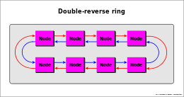
cc-NUMA system is a cluster of SMP systems, called "NODEs", connected via a connection network that can be a link that can be single or double-reverse ring, or multi-ring, point-to-point connections[23][30] or a mix of these (e.g. IBM Power Systems[21][47]), bus interconnection (e.g. NUMAq[48]), crossbar, segmented bus (NUMA Bull HN ISI ex Honeywell[49]), Mesh router, etc..
Examples of interconnections:


The main characteristic of cc-NUMA system is to have an unique shared global memory distributed in each node
directly accessed from all the processors of all the nodes
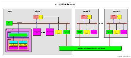
In a NUMA system, the access from a processor to a remote memory of a remote node, is slower compared to the access to its local memory. For this reason this system is called NUMA (Non Uniform Memory Access).
NUMA is also called Distributed Shared Memory (DSM) architecture.[50]
Each node usually is a SMP system, where a processor can be a single processor or a multi-core processor or mix of this two or any other kind of architecture. The fig. aside is just an example.
The difference in access time from local and remote can be also of an order of magnitude, depending on the kind of the connection network used (faster in segmented bus, crossbar and point-to-point interconnection, slower in serial rings connection).
Remote cache
Terminology:
(from a node point view)
- Local memory – memory of the node
- Remote memory – memory of the other remote nodes
- Local data – data stored in local memory
- Remote data – data stored in remote memories
- Remote cache – cache of the node that stores data read from remote memories
- Local caches (L1-L3) – caches of the node that stores local and remote data
To reduce the difference in access time from local and remote data, a Remote cache can be used. This cache stores data read from the other remote memories. Usually this cache is a shared inclusive cache with MESI protocol. L1-L3 caches can be extended MESI type (e.g. R-MESI, RT-MESI, etc.). Each remote data that is stored in local L1-L3 caches, is stored also in this cache (for inclusivity). This cache is the 4th level for the remote data only (cache of remote memories), while L1-L3 caches can stored instead local and remote data (cache of the node related to the global memory). From a node internal point of view this cache can see as an extension of the local memory (remote data stored locally).
Because the function of this cache is to reduce the remote access time at least as the own local memory access time, an hybrid technology may be used – SRAM for directory, DRAM for data cache.[51] This solution allows to implement a large cache as required from these systems.
The Remote cache can store both instructions (code) and data (as operands), but usually only the data is stored. The access to private data, such as code and the stack, often can be performed locally by copying the code (code replication) from another node (increasing efficiency).[52]
cc-NUMA cache coherency
Cache coherency in NUMA system (cc-NUMA) is obtained by using a Directory-based – Message-passing protocol. This approach was proposed for the first time by Censier and Feaultrier[53] and described also in "The Directory-Based Cache Coherency Protocol for DASH Multiprocessor ".[54]
Since usually not all the nodes are access at the same time on the same data, the coherence control can be done much more effectively if this is made in selective mode only on the involved nodes.
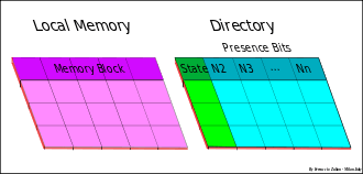
Cache coherency at system level (inter-node) is therefore maintained by a directory-based protocol using a directory associated to each local memory that keeps track of the global state of all memory blocks of its local memory, and an indicator (node "indicator bit") in order to indicate which node has the memory blocks cached in its remote cache. Coherency inside the node, instead, is based on the bus-snoopy scheme.
Each directory entry has N-1 node indicator bit and three global states associated with each memory block that are a copy of all the remote caches states.
- Invalid (I) or Uncached (U) – no cached by any other node than the home local memory
- Shared-Remote (S) – valid copies exist in other nodes
- Exclusive-Remote (E) or Dirty-Remote – the block is cached only in one node. In MESI protocol the block in the remote node can be Clean-Exclusive or Dirty. The switch between Clean-Exclusive to Dirty is made only locally without inform the "home directory", that is the directory of the local memory owner of the block. In MSI protocol the block in remote node can be only in Dirty state also if it is clean.[54][55]
* The remote cache stores data read from the remote memories of other nodes.
* The local memory directory holds trace of the local data and their state, read from the local memory
that are stored in remote caches of the other nodes.[56]
- Warning – not to be confused the "local memory directory" with the "directory of the remote cache". The first contains information on the local data, the second on the remote data
The are four possible situations for a node:
- Local memory read
- Local memory write
- Remote memory read
- Remote memory write
Local memory read
- - A local memory read transaction from a processor of a same node is snooped and handled in same way like with a normal SMP system.
- - L3 miss
- - In case of L1-L3 miss, the transaction is snooped on the System Bus by all the other local L3 caches and by the "directory of the local memory", in this case to verify if the snooped data is present on the other remote caches and in which nodes. The local memory directory is seen and handled as a directory of an extra cache, and more precisely as a "shared directory" of all the remote caches of the remote nodes. The only difference regarding the local L3 caches (composed of directory+data) is that the data and "Tag" of the global remote caches are not stored on the same node of the directory, but distributed on the other remote nodes.The communication between local memory directory and remote caches is made by a point-to-point or broadcasting Message-passing protocol by using the "Indicator bit" vector (the field of the bit indicators of the nodes).
- - If in local memory directory the state of the data is E (exclusive), a message is sent only to the remote cache of the node where the data is cached and wait for the response because the cache could be "Dirty".
- - If the data is Dirty, the data is sent back to the home and handled as if it came from a local cache with the exception that the "Shared-Dirty" is not allowed between nodes in protocol like MOESI. It could be allowed only in T-MESi type with the "owner" only in the "home" (Dirty-Owner" migration to home), but usually the "Dirty-intervention" and "Shared-clean intervention" between nodes is not used (e. g. POWER4 IBM protocol)
- - The state of the remote cache as well as the state of the associated L1-L3 are set to "Shared" and the state of the local memory directory is changed in S
- - If in local memory directory the state of the data is E (exclusive), a message is sent only to the remote cache of the node where the data is cached and wait for the response because the cache could be "Dirty".
- - If the data is stored in a L3 "owner" cache, the data is supplied by this cache (that can be "shared-clean owner" or "dirty-owner")
- - else from local memory
Local memory write
- - Hit Shared in L3
- - If there is a hit S in L3, an "Invalidate" transaction is sent to the bus to invalidate all the shared copy. If in local memory directory there are some node with S state, an invalidate transaction is sent to each node having a copy cached by using the node indicator stored in local memory directory.
- - Hit Esclusive in L3
- - The write is made locally in L1-L3 (for the inclusivity) as usually. The cache are set (or remain) "Dirty"
- - Miss
- - As with a "local memory read miss" with a command of "Invalidate" (RWITM), then as with a "write hit Exclusive"
Remote memory read

- - Miss
- - A remote memory read transaction (for a remote data) is snooped by all the L3 cache and by the remote cache of own node.
- - If there is a L3 cache "owner" the data is supplied this cache
- - else if "hit" in remote cache, the data is supplied by this cache
- - else a remote read request is sent to the node "home" of the data. The ""home" node handles this request in the same way like with an internal request. The only difference is that the data is sent instead to the requesting node. The requesting cache is set "Shared"
- - In case of "Dirty" data in an other node different of the "home", the "home" requires the data from this node as described in "Local memory read miss" operation in case of E state in local memory directory, then the data is sent to requesting node. Example: node "A" requires the data to the "home" "B". "B" requires the data to the node "C" having the data "Dirty". Node "C" sends the data to the "home" node "B" (copy back) then "B" forward the data to the node "A". "A" and "C" are set "Shared" as well as the home local memory directory.
Remote memory write
- - Hit "Exclusive" in L3
- - The write is performed locally as in a normal local "local write hit exclusive"
- - Hit "Shared" in L3
- - An invalidate transactions is sent to the data "home", then the requesting node wait for the permission to write. The "home" forward the invalidate transaction to all the nodes having the data, then it sends a write permission to the requesting node. Two simultaneous write in different nodes are so synchronized.
- - Miss
- - Like with "remote read miss" with an invalidate command (RWITM), then as a "local write hit exclusive"
Shared cache – coherency protocol
Typically used in Multi-core systems for coherency and cost reduction (space save).
Multi-core systems
(core = integrated processor)
Multi-core system, called chip multiprocessors, multicore chips, and many-core chips, is a special kind of multiprocessor where all processors are on the same chip (MCM – Multi-Chip Module)[57][58]
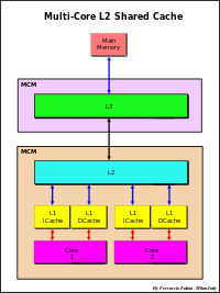

Multi-core processors are MIMD systems: different cores execute different threads (Multithread/Multiple Instructions – parallel execution on the same Context (computing) of small sequence of programmed instructions), operating on different parts of memory (Multiple Data).
A common solution of Multi-core systems implementation make use of multi-level inclusive shared cache to maintain data coherency.
Inclusivity force data to be coherence. Data stored in L1 are stored also in L2 (and in L3 if used). Any L1 changing must be reported in L2 cache and also in L3. If L2 is update or invalidate also all L1 must invalidated or updated (same relation between L2-L3).
Cache coherency is maintained by using a centralized cache controller on shared cache. Shared cache can be L2, or L3 if L2 is a private cache.
The coherency protocol is based on the point-to-point message-passing protocol type as described in cc-NUMA system. The difference is only in directory that in cc-NUMA system is related to the memory and not to the shared cache.
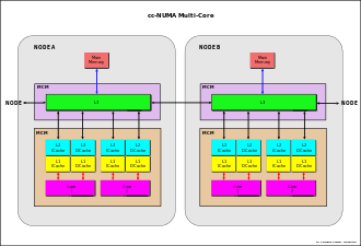
There are two kinds of implementation. Message broadcasting to all or only to the specific L1 cache that stores the data. In the first case the cache coherency protocol is a snoopy-type cache coherency. The shared cache acts as bridge, in substitution of the system bus, forwarding the transaction to all L1 caches for snooping, only if needed, that is when the data is not exclusive in shared cache. In the second case, in directory of the shared cache there is a "indicator bit" for each L1 cache to remember which L1 may have the data (Intel Nehalem[43]).
cc-NUMA in multi-core systems
Multi-core systems can be connected together to form a NUMA system. The coherency is guaranteed through a message-passing between the several L3 shared-caches of the several nodes (see for instance Intel Nehalem,[43] AMD Opteron,[23][30][59] MCM Interconnections Power5 IBM,[47][60] etc..
Stack cache
Overview
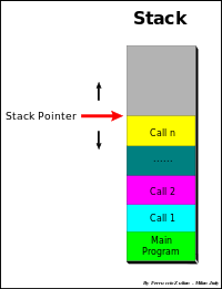
In a processor there are some very fast small memories called registers, handled by the software, to store temporary data.
In structured software, is frequent the use of some software routines called procedures to performs a specific task, subroutine or function. Also these procedures may be nested to any level, that is these subroutines in turn can call the other procedures or functions. These procedures make use of the same internal registers in independent mode from to the calling program. Therefore, before to make a Call (procedure call ), it is needed to save the these registers and parameters (local variables, return address point, etc.) used by the calling program, informations that will be recovered when returned to the calling program. These information are stored, by the software in memory in dedicate area of the process segment. This area is called Stack. A stack is always a push-down list, meaning that as new requests come in, they push down the old ones related to the Stack Pointer. Actually the list is fixed and it is the stack pointer that moves, up in save operation, down in restore operation. Another way of looking at a push-down list, or stack, is that the program always takes its next item to handle from the top of the stack (LIFO = Last In – First Out). The name Stack is borrowed from the name of the vertical dishes container, with a spring on the bottom, used at the beginning of the 20th century in the old London restaurants, with a spring on the button so that it was the bottom that was lowered or raised, putting or removing the dishes, while the last dishes was always fixed in the top.
To speed up the Call/Return operations, some processors make use of the ''Register windows (sPARC,[61][62][63] AMD 29000, Intel i960). In these systems a set of registers (windows) is reserved for each Call (from 2 to up 32 windows). In these systems it is not needed therefore to save any registers, so that the Call and Return operations are very fast, change only the set registers selection.
Stack cache implementation
An alternative solution is the Stack Cache.[64][65][66][67][68][69]
Data cache suffers, in general, from a limited hit rate (in the range of 80-90 % for business applications[2]) caused by a non-homogeneous and random data. Significant increase in performance is achieved by using separated data caches for normal data and for stack data.
A stack cache (S-Cache) is intended to maintain a separated cache from L1 data cache (D-cache)
that is accessed in predictable stack-like fashion.
Due to serial characteristics of the stack data, a stack cache can be indexed as a contiguous buffer of memory, which means it can be implemented as a direct-mapped cache.
The stack cache prevents the data stack to be replaced by the normal data. In this way the stack cache can be reach a hit rate near to 100%.[65][70]
An optimization can be obtained by using a L1 Set Associative cache and reserving one of a set cache for the data stack data (Honeywell Bull Systems[71]). This set is not exclusive reserved for the stack data, but the variable free area not used by the stack data, can be used for the normal data. This means that this set is used for the normal data as in usual mode but with the only restriction that the normal data cannot replace the stack data.
Virtual, physical, and pseudo virtual addressing
MMU
MMU (Memory Management Unit) is the unit to manage the MM accesses. The main functions are:
- Translation of address from virtual to physical
- Management of TLB miss
- Accesses permission checking of the cache line and of the MM:
- 1 – Supervisor/User mode
- 2 – writing protection
TLB
The Virtual memory is the space seen from a process. Generally this space is much greater than the physical memory. This space is segmented in pages of a prefixed size. The Page table (generally loaded in memory) keeps track of where the virtual pages are loaded in the physical memory. The TLB (Translation Lookaside Buffer or "Page Table Cache" or also "Page-Translation Cache") is a cache of the Page table (PTE), that is only a subset of its content is stored in the TLB. The TLB, like with the cache memory, may be '"separated" Instructions (ITLB) and Data (DTLB) or "unified", as well as may be Direct Mapped or Set Associative or Fully Associative. Generally the organization follows the same organization of the associated cache memory, but may be organized in independent ways from this (see TLB). Like with cache, to increase the efficiency it can be used a TLB dual-level by adding an L2 TLB (e.g. Intel Nehalem[43]).

The cache can be addressed in physical or virtual mode. There are pros and cons for both implementations, but normally the physical addressing is that commonly used.
Virtual addressing
In fig. "Virtual Space Address Structure" it is shown an example of virtual address with 4 GB virtual space, 4 MB cache, 4 KB page size and 256 B cache line size.

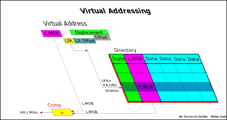
Virtual or Logical Space is divided in pages. MSB + PA form the page address of virtual space VPA (Virtual Page Address). Also the cache is divided in pages.
The cache stores a subset of the virtual space pages. It is addressed by the Index that is formed by PA + PA Offset, where PA (Page Address) is the page address of the cache and PA Offset is the address of the cache line of a page, while Offset is the address at the byte level of a cache line.
In virtual or logical addressing, a cache is directly addressed by using the Index without having to convert before the address from virtual to physical. Also the TAGs are virtual (logical MSB). This type of addressing is known as Virtual Index – Virtual TAG – VIVT.
In a multiprocessing environment, several different logical addresses of different contexts or processes may refer to the same physical address, or the same logical address of a process may maps several different physical addresses, causing a coherency problem, while on the contrary, within the same context, the same logical address is always related to the same physical address.
There are three possible solutions:
- flushing the cache to every context switch
- add in cache an address space ID (ASID – Address Space IDentifier) or Context Number (CTX) or Process Number (PN), to distinguish the various processes/contexts[72]
- add in cache the correspondent physical TAG (MSB) that must be checked with the physical MSB obtained by the TLB (accessed in parallel - "look aside"), to verify the correct association between virtual-to-physical address (Virtual Index – Physical TAG – VIPT addressing).
Coherency problem
Because different logical addresses of different contexts may refer to the same physical address (data sharing), more than one cache location may be store the same data, causing a coherency problem in case of write. Only one location would be updated.
There are two main solutions[73]
- 1 – Synonym prevention
- - Software prevent or avoid synonyms
- 2 – Dynamic synonym detection
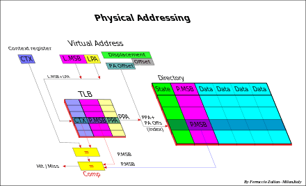
- - Hardware support can relieve the software of all or most of the task of maintaining consistency in the presence of synonyms
In any case the cache must be always flushed when the virtual-to-physical mapping is changed (for instace in case of page replacement).
Physical addressing
In physical addressing, first the TLB (*) is addressed by using the virtual address L.MSB + LPA, then the physical address (PPA) obtained from the TLB (plus PPA Offset) is used to address the cache. Only the part of Virtual address that differs from the Physical address is translate, that is the L.MSB and the LPA.
The TLB is a cache of the Page table and is handled as a normal cache with in addition that the CTX associates to the logical address is compared with CTX stored in TLB because changing context changes also the association LPA-PPA (see virtual addressing).
This solution (Physical Index – Physical TAG – PIPT addressing) is much simpler and avoid any aliasing problem but it is slower because first requires access to the TLB.
(*) – At the beginning the cache size used was small and equal to the page size, therefore the virtual and physical "index" were coinciding and the TLB was accessed in parallel (so that the name "look aside") only to check the physical MSBs, as in virtual addressing.
Pseudo-virtual addressing
This solution gives to all the advantages of both the previous solutions.
* This approach is based on the spatial locality principle.
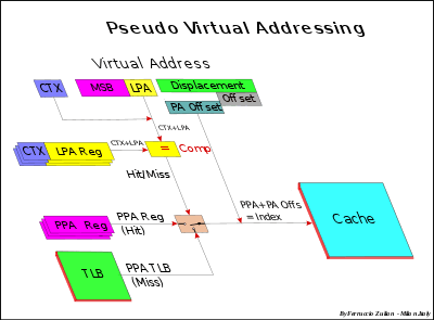
Referring to the fig. Virtual Space Address Structure, the address virtual/logical "Index" is divided in two parts: Logical Page Address (LPA) (or Page number) and Page Offset (cache line address within the page). The Offset is the address (at byte level) within the cache line.
The Virtual and the Physical Page Offset coincide (as well as, of course, the Offset ). Virtual and Physical address differ for the L.MSB and for the LPA. The TLB translates the logical L.MSB and Logical Page Address (LPA), respectively in physical P.MSB and in Physical Page Address (PPA). PPA + LPA Offset form the physical Index that is used to address the cache.
- Spatial locality means that if a access is made in a page there is a high probability that next access is made in the same.
Separately for Instructions, Data and for Stack data (if the Stack is used), the probability that the next access is in same page of a previous access is very high due to a very large spatial locality (4 KB or more compared, for instance, to a more small cache line size).
The previous Logical Page address (LPA) with its Context Number (CTX) and the correspondent Page Physical Address (PPA) are stored dedicated registers.
On the next access, the new Logical Page address (LPA) with its Context Number (CTX) is compared with the previous LPA. If match (hit) the correspondent Page Physical address (PPA) register is used to directly address the cache, without the necessity to access to TLB, as like it happens in case of virtual addressing (from which the name Pseudo Virtual addressing).
In case of miss, the PPA is supplied from the TLB, like with the physical addressing without any penalty regarding this last one.
This approach is effective if a "LPA-PPA" set registers is reserved for each type of function: one for instruction address, two for data operands (each instruction can have up to two operand addresses) and eventually one for data stack. Moreover, to increase the efficiency in multithreading systems, a group of dedicated "LPA-PPA" registers can be used one for each thread.
Note – These registers can be see as a L1 cache of TLB with only one entry, separated for each type of data (instructions, data1, data,2 stack) and for each tread, that is a L1 TLB cache made by registers therefore very high speed.
With this solution, practically without added cost, in almost all the cases, and particularly for instructions and sequential data strings, the addressing is performed in physical mode but without need to wait for the address translation virtual-to-physical, such like in virtual addressing, but without need to flush the cache in case of page replacement, as required in virtual addressing, and without any coherency problem.
See also
References
- 1 2 3 4 5 The POWER4 Processor Introduction and Tuning Guide par. 2.4 – http://www.redbooks.ibm.com/redbooks/pdfs/sg247041.pdf
- 1 2 3 4 Architecture Analysis of Tightly Coupled Multiprocessor Systems – F. Zulian Honeywell (Bull Italia 1987)
- ↑ Athlon II/Phenom II L3 cache – http://www.tomshardware.com/reviews/athlon-l3-cache,2416.html
- 1 2 IBM RS/6000 Scientific and Technical Computing: POWER3 Introduction and Tuning Guide (Ch. 7.1 p.88) – http://www.redbooks.ibm.com/pubs/pdfs/redbooks/sg245155.pdf)
- ↑ Performance Evaluation of Cache Replacement Policies for the SPEC CPU2000 Benchmark Suite – http://www.ece.uah.edu/~milenka/docs/milenkovic_acmse04r.pdf
- ↑ Performance Modeling for Computer Architects – https://books.google.com/books?id=SbvE5KM6AioC&pg=PA217&lpg=PA217&dq=cache+memory+replacement+policy&source=bl&ots=Ar6QmC29ss&sig=rYaqNOkNHavDIhrHvwTvdQ7eRFw&hl=it&sa=X&ei=XcI_U5PoFMOMtQajnoHACg&ved=0CFAQ6AEwBDgK
- ↑ Architecture Programmer's Manual "3.9.4 Cache Operation" – http://developer.amd.com/wordpress/media/2012/10/24593_APM_v21.pdf
- ↑ Itanium 2 Processor Microarchitecture – http://www.ece.ucdavis.edu/~akella/270W05/itanium%202.pdf
- ↑ Intel Iris Pro 5200 Graphics Review: Core i7-4950HQ Tested – http://www.anandtech.com/show/6993/intel-iris-pro-5200-graphics-review-core-i74950hq-tested/3
- ↑ IBM e server pSeries 690 – http://www.research.ibm.com/haifa/projects/verification/RB_Homepage/ps/p690.pdf
- ↑ Shimpi, Lal (June 1, 2013). "Intel Iris Pro 5200 Graphics Review: Core i7-4950HQ Tested by Anand". AnandTech. Archived from the original on 2013-06-07.
- 1 2 3 Comparing Cache Architectures and Coherency Protocols on x86-64 Multicore SMP Systems – http://people.freebsd.org/~lstewart/articles/cache-performance-x86-2009.pdf
- ↑ RS/6000 Scientific and Technical Computing: POWER3 Introduction and Tuning Guide – http://www.redbooks.ibm.com/redbooks/pdfs/sg245155.pdf (Ch. 2.1 pp. 7-8)
- ↑ Data Caches for Superscalar Processors – http://pages.saclay.inria.fr/olivier.temam/files/eval/JNT97.pdf
- ↑ High Bandwidth Data Memory Systems for Superscalar Processors – ftp://ftp.cs.wisc.edu/pub/techreports/1990/TR968.pdf
- ↑ Functional Principles of Cache Memory – http://alasir.com/articles/cache_principles/cache_multiporting.html
- ↑ Comparing Multiported Cache Schemes – https://pdfs.semanticscholar.org/c75f/b2158ab82bbc347bcd6f04ba2bf86f448296.pdf
- ↑ On High-Bandwidth Data Cache Design for Multi-Issue Processors – http://web.eecs.umich.edu/~taustin/papers/MICRO30-bwcache.pdf
- ↑ IBM RS/6000 Scientific and Technical Computing: POWER3 Introduction and Tuning Guide (Ch 7.1 p. 89) – http://www.redbooks.ibm.com/redbooks/pdfs/sg245155.pdf
- ↑ IBM RS/6000 Scientific and Technical Computing: POWER3 Introduction and Tuning Guide Ch. 2.1 p. 7 – ch 7.1 p.89 – http://www.redbooks.ibm.com/redbooks/pdfs/sg245155.pdf
- 1 2 3 4 5 6 "POWER4 System Microarchitecture", http://www.cc.gatech.edu/~bader/COURSES/UNM/ece637-Fall2003/papers/TDF02.pdf
- ↑ John L. Hennessy and David A. Patterson. CompzLter Architecture: A Quantitative Approach, 2nd Edition. Morgan Kaufmann Publishers Inc., 1996.
- 1 2 3 4 AMD Opteron Shared Memory MP Systems – http://www.cse.wustl.edu/~roger/569M.s09/28_AMD_Hammer_MP_HC_v8.pdf
- 1 2 Multi-processor system with shared memory – http://www.freepatentsonline.com/5701413.html
- ↑ Method for transferring data in a multiprocessor computer system with crossbar interconnecting unit – http://www.google.com/patents/EP0923032A1?cl=en
- ↑ Specification and Verification of the PowerScale Bus Arbitration Protocol: An Industrial Experiment with LOTOS, Chap. 2, Pag. 4 – ftp://ftp.inrialpes.fr/pub/vasy/publications/cadp/Chehaibar-Garavel-et-al-96.pdf
- 1 2 3 4 5 6 7 8 9 10 11 12 13 14 15 16 , Archibald, J. and Baer, J. 1986 – Cache coherence protocols: evaluation using a multiprocessor simulation model. ACM Trans. Comput. Syst. 4, 4 (Sep. 1986), 273-298 – http://ctho.org/toread/forclass/18-742/3/p273-archibald.pdf.
- 1 2 MPC7400 RISC Microprocessor User's Manual – http://pccomponents.com/datasheets/MOT-MPC7400.PDF
- 1 2 3 4 5 6 7 Cache-coherency protocol with recently read state for data and instructions – IBM patent – http://www.google.com/patents/US5996049
- 1 2 3 4 5 An Introduction to the Intel® QuickPath Interconnect – http://www.intel.ie/content/dam/doc/white-paper/quick-path-interconnect-introduction-paper.pdf
- 1 2 Forward state for use in cache coherency in a multiprocessor system – Intel -https://www.google.com/patents/US6922756
- ↑ IBM PowerPC 476FP L2 Cache Core Databook – https://www-01.ibm.com/chips/techlib/techlib.nsf/techdocs/8D5342097498C81A852575C50078D867/$file/L2CacheController_v1.5_ext_Pub.pdf
- 1 2 3 4 5 6 7 Cache Coherency Protocol Including an HR State – IBM patent – https://www.google.com/patents/US6275908
- 1 2 3 4 5 6 7 8 Cache Coherency Protocol with Tagged State for Modified Values – IBM patent – http://www.google.com/patents/US6334172
- ↑ MPC750UM/D 12/2001 Rev. 1 MPC750 RISC Microprocessor Family User's Manual – http://www.freescale.com/files/32bit/doc/ref_manual/MPC750UM.pdf
- 1 2 3 4 Pentium Pro and Pentium II System Architecture pg. 160 – Di T. Shanley – https://books.google.com/books?id=MLJClvCYh34C&pg=PA160&lpg=PA160&dq=Pentium+protocol+cache&source=bl&ots=gaOu-EvaTy&sig=QQEM1krp-H_0KUhi5Ti2bmxU2kU&hl=it&sa=X&ei=Zt6KT7icG8TE4gShzaDwCQ&ved=0CDcQ6AEwAg#v=onepage&q=Pentium%20protocol%20cache&f=false
- ↑ AMD64 Technology – AMD64 Architecture Programmer's Manual Volume 2: System Programming – http://developer.amd.com/wordpress/media/2012/10/24593_APM_v21.pdf
- 1 2 3 Sweazey, P., and Smith, A. J. A class of compatible cache consistency protocols and their support by the IEEE Futurebus. In Proceedings of the 13th International Symposium on Computer Architecture. IEEE. New York, 1986, pp. 414-423.) – http://pdf.aminer.org/000/419/524/a_class_of_compatible_cache_consistency_protocols_and_their_support.pdf
- ↑ Mark S. Papamarcos and Janak H. Patel. In ISCA '84: Proceedings of the 11th annual international symposium on Computer architecture, pages 348-354, New York, NY, USA, 1984. ACM – http://www.researchgate.net/publication/220771512_A_Low-Overhead_Coherence_Solution_for_Multiprocessors_with_Private_Cache_Memories/file/50463519b8d139e451.pdf
- 1 2 Using cache memory to reduce processor-memory traffic". Proceedings of the 10th annual international symposium on Computer architecture – ISCA '83. International Symposium on Computer Architecture: Stockholm, Sweden, June 13–17, 1983.pp. 127-128 – http://courses.cs.vt.edu/cs5204/fall11-kafura/Papers/TransactionalMemory/Goodman-SnoopyProtocol.pdf
- 1 2 Advanced Computer Architecture, 2E pg. 301 – Di Hwang – https://books.google.com/books?id=m4VFXr6qjroC&pg=PA301
- 1 2 3 4 Cache memory and related consistency protocol, Inventor Ferruccio Zulian, Bull HN ISI – http://www.google.com/patents/EP0396940B1?cl=en
- 1 2 3 4 5 Cache Organization and Memory Management of the Intel Nehalem Computer Architecture http://gec.di.uminho.pt/Discip/MInf/cpd1011/PAC/material/nehalemPaper.pdf
- ↑ David Kanter (2007-08-28), "The Common System Interface: Intel's Future Interconnect", Real World Tech: 5, retrieved 2012-08-12
- ↑ Optimizing the MESI Cache Coherence Protocol for Multithreaded Applications on Small Symmetric Multiprocessor Systems – http://tibrewala.net/papers/mesi98/
- ↑ Handy, Jim. "Cache Memory Book", Academic Press, Inc., 1998, p. 130, p. 208 – https://books.google.com/books?hl=it&id=-7oOlb-lCpMC&q=208
- 1 2 IBM POWER Systems Overview
- ↑ SourceForge – http://lse.sourceforge.net/numa/faq/system_descriptions.html
- ↑ Bull HN F. Zulian – A. Zulian patent – Computer system with a bus having a segmented structure – http://www.freepatentsonline.com/6314484.html
- ↑ NUMA Architecture – http://www.dba-oracle.com/real_application_clusters_rac_grid/numa.html
- ↑ Data-processing system with CC-NUMA (cache-coherent, non-uniform memory access) architecture and remote cache incorporated in local memory - http://www.freepatentsonline.com/6243794.html
- ↑ Directory-based CacheCoherence – Parallel Computer Architecture par. 1.3.2 pg. 48 – http://www.dte.eis.uva.es/Docencia/ETSII/SMP/archivos/archibak/culler.pdf
- ↑ A new Solution to Coherence Problems in Multicaches Systems – Censier and Feaultrier – http://www.cs.auckland.ac.nz/courses/compsci703s1c/resources/Censier.pdf
- 1 2 3 Proceedings of the 17th Annual International Symposium on Computer Architecture, IEEE 1990, pages 148-159; D. Lenosky et al: The Directory-Based Cache Coherency Protocol for DASH Multiprocessor – http://www.cse.wustl.edu/~roger/569M.s09/p148-lenoski.pdf
- ↑ Directory-based CacheCoherence – Parallel Computer Architecture ch. 8 pg. 513 – http://www.dte.eis.uva.es/Docencia/ETSII/SMP/archivos/archibak/culler.pdf
- ↑ SourceForge – http://lse.sourceforge.net/numa/faq/
- ↑ http://scholar.google.it/scholar_url?url=http://minds.wisconsin.edu/bitstream/handle/1793/60554/TR1593.pdf%3Fsequenc&hl=it&sa=X&scisig=AAGBfm3Tfz0tL0HBvHhv_6mCWgvMIZhsxg&oi=scholarr&ei=pXGmVPnBAsn7Uti3g7AL&ved=0CCEQgAMoADAA
- ↑ <http://scholar.google.it/scholar_url?url=http://www.itu.dk/people/jhh/thesis/references/36%2520-%2520Chip%2520Makers%2520Turn%2520to%2520Multicore%2520Processors.pdf&hl=it&sa=X&scisig=AAGBfm26PHbY3VJRZqQtLux3ac90MmK1rQ&oi=scholarr&ei=pXGmVPnBAsn7Uti3g7AL&ved=0CCIQgAMoATAA
- ↑ Cache Coherence Techniques for Multicore Processors – Michael R. Marty – http://research.cs.wisc.edu/multifacet/theses/michael_marty_phd.pdf
- ↑ Of NUMA on POWER7 in IBM Mark Funk, Rick Peterson – http://mrfunk.info/?page_id=74
- ↑ Understanding stacks and registers in the Sparc architecture(s) – http://ieng9.ucsd.edu/~cs30x/sparcstack.html
- ↑ The SPARC Architecture – Jingke Li – http://web.cecs.pdx.edu/~herb/cs322s10/Sparc_Architecture.pdf
- ↑ The SPARC Architecture Manual Version 8 – http://www.gaisler.com/doc/sparcv8.pdf
- ↑ Stack data cache having a stack management hardware with internal and external stack pointers and buffers for handling underflow and overflow stack – http://www.google.com/patents/US5107457
- 1 2 Implementing a Stack Cache – AMD architecture – http://www.owlnet.rice.edu/~elec525/projects/SCreport.pdf
- ↑ Register Allocation for Free: The C Machine Stack Cache – Massachusetts Institute of Technology – http://dl.acm.org/citation.cfm?id=801825&dl=ACM&coll=DL&CFID=849908598&CFTOKEN=97843355
- ↑ Stack Cache for Block-Structured Programs – http://comjnl.oxfordjournals.org/content/37/7/610.full.pdf
- ↑ The Mechanization of a Push-down Stack" - C. B. Carlson (AFIPS Conf. Proc., V. 24, 1963)
- ↑ Strategies for Managing the Register file in RISC" - Tamir and C. H. Sequin (IEEE Transection on Computers, Vol. C-32, No. 11, November 1983)
- ↑ Implementing a Stack Cache – http://www.owlnet.rice.edu/~elec525/projects/SCpresentation.pdf
- 1 2 Cache memory having pseudo virtual addressing – Honeywell Bull Italia – https://www.google.com/patents/US5165028
- ↑ High-speed memory and memory management system – Sun Microsystems – http://www.google.com.tr/patents/US4550368
- ↑ Virtual-Addrerss Caches – http://www.ece.umd.edu/class/enee646.F2007/Cekleov1.pdf