Centrifugal pump
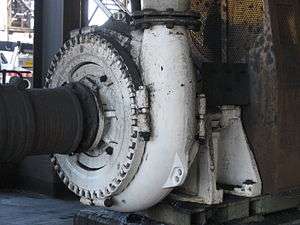
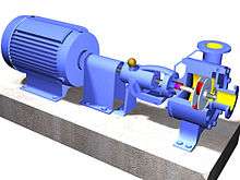
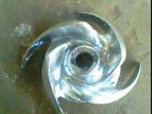
Centrifugal pumps are a sub-class of dynamic axisymmetric work-absorbing turbomachinery.[1] Centrifugal pumps are used to transport fluids by the conversion of rotational kinetic energy to the hydrodynamic energy of the fluid flow. The rotational energy typically comes from an engine or electric motor. The fluid enters the pump impeller along or near to the rotating axis and is accelerated by the impeller, flowing radially outward into a diffuser or volute chamber (casing), from where it exits.
Common uses include water, sewage, petroleum and petrochemical pumping; a centrifugal fan is commonly used to implement a vacuum cleaner. The reverse function of the centrifugal pump is a water turbine converting potential energy of water pressure into mechanical rotational energy.
History
According to Reti, the first machine that could be characterized as a centrifugal pump was a mud lifting machine which appeared as early as 1475 in a treatise by the Italian Renaissance engineer Francesco di Giorgio Martini.[2] True centrifugal pumps were not developed until the late 17th century, when Denis Papin built one using straight vanes. The curved vane was introduced by British inventor John Appold in 1851.
How it works
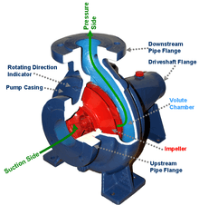
Like most pumps, a centrifugal pump converts rotational energy, often from a motor, to energy in a moving fluid. A portion of the energy goes into kinetic energy of the fluid. Fluid enters axially through eye of the casing, is caught up in the impeller blades, and is whirled tangentially and radially outward until it leaves through all circumferential parts of the impeller into the diffuser part of the casing. The fluid gains both velocity and pressure while passing through the impeller. The doughnut-shaped diffuser, or scroll, section of the casing decelerates the flow and further increases the pressure.
Description by Euler
A consequence of Newton’s second law of mechanics is the conservation of the angular momentum (or the “moment of momentum”) which is of fundamental significance to all turbomachines. Accordingly, the change of the angular momentum is equal to the sum of the external moments. Angular momentums ρ×Q×r×cu at inlet and outlet, an external torque M and friction moments due to shear stresses Mτ are acting on an impeller or a diffuser.
Since no pressure forces are created on cylindrical surfaces in the circumferential direction, it is possible to write Eq. (1.10) as:[3]
- (1.13)

Euler's pump equation
Based on Eq.(1.13) Euler developed the head pressure equation created by the impeller see Fig.2.2
- (1)

- (2)

In Eq. (2) the sum of 4 front element number call static pressure,the sum of last 2 element number call velocity pressure look carefully on the Fig 2.2 and the detail equation.
Ht theory head pressure ; g = between 9.78 and 9.82 m/s2 depending on latitude, conventional standard value of exactly 9.80665 m/s2 barycentric gravitational acceleration
u2=r2.ω the peripheral circumferential velocity vector
u1=r1.ω the inlet circumferential velocity vector
ω=2π.n angular velocity
w1 inlet relative velocity vector
w2 outlet relative velocity vector
c1 inlet absolute velocity vector
c2 outlet absolute velocity vector
Velocity Triangle
The color triangle formed by velocity vector u,c,w called "velocity triangle". this is an important role in old academic, this rule was helpful to detail Eq.(1) become Eq.(2) and wide explained how the pump works.
Fig 2.3 (a) shows triangle velocity of forward curved vanes impeller ; Fig 2.3 (b) shows triangle velocity of radial straight vanes impeller. It illustrates rather clearly energy added to the flow (shown in vector c) inversely change upon flow rate Q (shown in vector cm).
Efficiency factor
,

where:
- is the mechanics input power required (W)
- is the fluid density (kg/m3)
- is the standard acceleration of gravity (9.80665 m/s2)
- is the energy Head added to the flow (m)
- is the flow rate (m3/s)
- is the efficiency of the pump plant as a decimal


The head added by the pump () is a sum of the static lift, the head loss due to friction and any losses due to valves or pipe bends all expressed in metres of fluid. Power is more commonly expressed as kilowatts (103 W, kW) or horsepower (hp = kW*0.746). The value for the pump efficiency, , may be stated for the pump itself or as a combined efficiency of the pump and motor system.

Vertical centrifugal pumps
Vertical centrifugal pumps are also referred to as cantilever pumps. They utilize a unique shaft and bearing support configuration that allows the volute to hang in the sump while the bearings are outside the sump. This style of pump uses no stuffing box to seal the shaft but instead utilizes a "throttle bushing". A common application for this style of pump is in a parts washer.
Froth pumps
In the mineral industry, or in the extraction of oilsand, froth is generated to separate the rich minerals or bitumen from the sand and clays. Froth contains air that tends to block conventional pumps and cause loss of prime. Over history, industry has developed different ways to deal with this problem. In the pulp and paper industry holes are drilled in the impeller. Air escapes to the back of the impeller and a special expeller discharges the air back to the suction tank. The impeller may also feature special small vanes between the primary vanes called split vanes or secondary vanes. Some pumps may feature a large eye, an inducer or recirculation of pressurized froth from the pump discharge back to the suction to break the bubbles.[4]
Multistage centrifugal pumps

A centrifugal pump containing two or more impellers is called a multistage centrifugal pump. The impellers may be mounted on the same shaft or on different shafts. At each stage, the fluid is directed to the center before making its way to the discharge on the outer diameter.
For higher pressures at the outlet, impellers can be connected in series. For higher flow output, impellers can be connected parallel.
A common application of the multistage centrifugal pump is the boiler feedwater pump. For example, a 350 MW unit would require two feedpumps in parallel. Each feedpump is a multistage centrifugal pump producing 150 l/s at 21 MPa.
All energy transferred to the fluid is derived from the mechanical energy driving the impeller. This can be measured at isentropic compression, resulting in a slight temperature increase (in addition to the pressure increase).
Energy usage
The energy usage in a pumping installation is determined by the flow required, the height lifted and the length and friction characteristics of the pipeline. The power required to drive a pump (), is defined simply using SI units by:


where:
- is the input power required (W)
- is the fluid density (kg/m3)
- is the standard acceleration of gravity (9.80665 m/s2)
- is the energy Head added to the flow (m)
- is the flow rate (m3/s)
- is the efficiency of the pump plant as a decimal
The head added by the pump () is a sum of the static lift, the head loss due to friction and any losses due to valves or pipe bends all expressed in metres of fluid. Power is more commonly expressed as kilowatts (103 W, kW) or horsepower (kW = hp/0.746). The value for the pump efficiency, , may be stated for the pump itself or as a combined efficiency of the pump and motor system.
The energy usage is determined by multiplying the power requirement by the length of time the pump is operating.
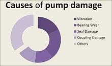
Problems of centrifugal pumps
These are some difficulties faced in centrifugal pumps:[6]
- Cavitation—the net positive suction head (NPSH) of the system is too low for the selected pump
- Wear of the impeller—can be worsened by suspended solids
- Corrosion inside the pump caused by the fluid properties
- Overheating due to low flow
- Leakage along rotating shaft.
- Lack of prime—centrifugal pumps must be filled (with the fluid to be pumped) in order to operate
- Surge
Centrifugal pumps for solids control
An oilfield solids control system needs many centrifugal pumps to sit on or in mud tanks. The types of centrifugal pumps used are sand pumps, submersible slurry pumps, shear pumps, and charging pumps. They are defined for their different functions, but their working principle is the same.
Magnetically coupled pumps
Magnetically coupled pumps, or magnetic drive pumps, vary from the traditional pumping style, as the motor is coupled to the pump by magnetic means rather than by a direct mechanical shaft. The pump works via a drive magnet, 'driving' the pump rotor, which is magnetically coupled to the primary shaft driven by the motor.[7] They are often used where leakage of the fluid pumped poses a great risk (e.g., aggressive fluid in the chemical or nuclear industry, or electric shock - garden fountains). They have no direct connection between the motor shaft and the impeller, so no gland is needed. There is no risk of leakage, unless the casing is broken. Since the pump shaft is not supported by bearings outside the pump's housing, support inside the pump is provided by bushings. The pump size of a magnetic drive pumps can go from few Watts power to a giant 1MW.
Priming
Most centrifugal pumps are not self-priming. In other words, the pump casing must be filled with liquid before the pump is started, or the pump will not be able to function. If the pump casing becomes filled with vapors or gases, the pump impeller becomes gas-bound and incapable of pumping. To ensure that a centrifugal pump remains primed and does not become gas-bound, most centrifugal pumps are located below the level of the source from which the pump is to take its suction. The same effect can be gained by supplying liquid to the pump suction under pressure supplied by another pump placed in the suction line.
Self priming centrifugal pump
Enough liquid for priming can be stored in a specially designed pump casing, resulting in a centrifugal pump that is self-priming. During priming the liquid is recirculated within the casing. Gas from the suction port mixes with the liquid in the pump. The impeller repeatedly ejects the mixture back into the casing. The liquid sinks to the bottom of the casing, where it reenters the pump along with more gas from the suction port. Gradually the gas is expelled from the pump into the discharge line, and the suction line fills with liquid. Normal centrifugal pump operation begins.[7] it is mostly used in centrifugal pump in which motor is not applicable to start the priming provides the pump to start because the rotor some time not pumps the fluid the priming act as storage tank in which the fluid is pumped to the centrifugal pump then it is started again to pump the fluid
See also
- Axial flow pump
- Effects of mach number and shock losses in turbomachines
- Net positive suction head (NPSH)
- Pump
- Seal (mechanical)
- Specific speed (Ns or Nss)
- Thermodynamic pump testing
- Turbine
- Turbopump
References
- ↑ Shepard, Dennis G. (1956). Principles of Turbomachinery. McMillan. ISBN 0-471-85546-4. LCCN 56002849.
- ↑ Reti, Ladislao; Di Giorgio Martini, Francesco (Summer 1963). "Francesco di Giorgio (Armani) Martini's Treatise on Engineering and Its Plagiarists". Technology and Culture. 4 (3): 287–298 (290). doi:10.2307/3100858.
- ↑ Gülich, Johann Friedrich (2010). Centrifugal Pumps (2nd ed.). ISBN 978-3-642-12823-3.
- ↑ Baha Abulnaga (2004). Pumping Oilsand Froth (PDF). 21st International Pump Users Symposium, Baltimore, Maryland. Published by Texas A&M University, Texas, USA.
- ↑ Moniz, Paresh Girdhar, Octo (2004). Practical centrifugal pumps design, operation and maintenance (1. publ. ed.). Oxford: Newnes. p. 13. ISBN 0750662735. Retrieved 3 April 2015.
- ↑ Larry Bachus, Angle Custodio (2003). Know and understand centrifugal pumps. Elsevier Ltd. ISBN 1856174093.
- ↑ "How a self-priming centrifugal pump works". Gorman-Rupp Company. November 21, 2005. Retrieved August 3, 2016.
Sources
External links
- Minimum Thermal Flow in Centrifugal Pumps - Chemical Engineering Site
| Look up Centrifugal pump in Wiktionary, the free dictionary. |
| Wikimedia Commons has media related to Centrifugal pumps. |