Cockcroft–Walton generator
The Cockcroft–Walton (CW) generator, or multiplier, is an electric circuit that generates a high DC voltage from a low-voltage AC or pulsing DC input. It was named after the British and Irish physicists John Douglas Cockcroft and Ernest Thomas Sinton Walton, who in 1932 used this circuit design to power their particle accelerator, performing the first artificial nuclear disintegration in history.[1] They used this voltage multiplier cascade for most of their research, which in 1951 won them the Nobel Prize in Physics for "Transmutation of atomic nuclei by artificially accelerated atomic particles". Less well known is the fact that the circuit was discovered much earlier, in 1919, by Heinrich Greinacher, a Swiss physicist. For this reason, this doubler cascade is sometimes also referred to as the Greinacher multiplier. Cockcroft–Walton circuits are still used in particle accelerators. They also are used in everyday electronic devices that require high voltages, such as X-ray machines, television sets, and photocopiers.
Design


The CW is a voltage multiplier that converts AC or pulsing DC electrical power from a low voltage level to a higher DC voltage level. It is made up of a voltage multiplier ladder network of capacitors and diodes to generate high voltages. Unlike transformers, this method eliminates the requirement for the heavy core and the bulk of insulation/potting required. Using only capacitors and diodes, these voltage multipliers can step up relatively low voltages to extremely high values, while at the same time being far lighter and cheaper than transformers. The biggest advantage of such circuits is that the voltage across each stage of the cascade is equal to only twice the peak input voltage in a half-wave rectifier. In a full-wave rectifier it is three times the input voltage. It has the advantage of requiring relatively low-cost components and being easy to insulate. One can also tap the output from any stage, like in a multitapped transformer.
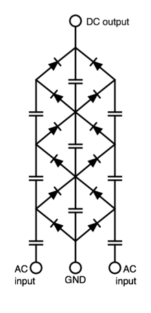
To understand the circuit operation, see the diagram of the two-stage version at right. Assume the circuit is powered by an alternating voltage Vi with a peak value of Vp. After the input voltage is turned on
- When the input voltage Vi reaches its negative peak −Vp, current flows through diode D1 to charge capacitor C1 to a voltage of Vp.
- When Vi reverses polarity and reaches its positive peak +Vp, it adds to the capacitor's voltage to produce a voltage of 2Vp on C1s righthand plate. Since D1 is reverse-biased, current flows from C1 through diode D2, charging capacitor C2 to a voltage of 2Vp.
- When Vi reverses polarity again, current from C2 flows through diode D3, charging capacitor C3 also to a voltage of 2Vp.
- When Vi reverses polarity again, current from C3 flows through diode D4, charging capacitor C4 also to a voltage of 2Vp.
With each change in input polarity, current flows up the "stack" of capacitors through the diodes, until they are all charged. All the capacitors are charged to a voltage of 2Vp, except for C1, which is charged to Vp. The key to the voltage multiplication is that while the capacitors are charged in parallel, they are connected to the load in series. Since C2 and C4 are in series between the output and ground, the total output voltage (under no-load conditions) is Vo = 4Vp.
This circuit can be extended to any number of stages. The output voltage is twice the peak input voltage multiplied by the number of stages N or equivalently the peak-to-peak input voltage swing (Vpp) times the number of stages

The number of stages is equal to the number of capacitors in series between the output and ground.
One way to look at the circuit is that it functions as a charge "pump", pumping electric charge in one direction, up the stack of capacitors. The CW circuit, along with other similar capacitor circuits, is often called charge pump. For substantial loads, the charge on the capacitors is partially depleted, and the output voltage drops according to the output current divided by the capacitance.
Operational characteristics
In practice, the CW has a number of drawbacks. As the number of stages is increased, the voltages of the higher stages begin to "sag", primarily due to the electrical impedance of the capacitors in the lower stages. And, when supplying an output current, the voltage ripple rapidly increases as the number of stages is increased. For these reasons, CW multipliers with large number of stages are used only where relatively low output current is required. These effects can be partially compensated by increasing the capacitance in the lower stages, by increasing the frequency of the input power and by using an AC power source with a square or triangular waveform. By driving the CW from a high-frequency source, such as an inverter, or a combination of an inverter and HV transformer, the overall physical size and weight of the CW power supply can be substantially reduced.
CW multipliers are typically used to develop higher voltages for relatively low-current applications, such as bias voltages ranging from tens or hundreds of volts to millions of volts for high-energy physics experiments or lightning safety testing. CW multipliers are also found, with a higher number of stages, in laser systems, high-voltage power supplies, X-ray systems, LCD backlighting, traveling-wave tube amplifiers, ion pumps, electrostatic systems, air ionisers, particle accelerators, copy machines, scientific instrumentation, oscilloscopes, television sets and cathode ray tubes, electroshock weapons, bug zappers and many other applications that use high-voltage DC.
Image gallery

See also
| Wikimedia Commons has media related to Cockcroft-Walton generators. |
A similar circuit is the Marx generator, which has the same "ladder" structure, but consists of resistors, capacitors and spark gaps. The Marx generator produces short pulses, whereas the CW generator produces a constant DC.
Notes
Further reading
- J. D. Cockcroft and E. T. S. Walton, Experiments with High Velocity Positive Ions.(I) Further Developments in the Method of Obtaining High Velocity Positive Ions, Proceedings of the Royal Society A, vol. 136, pp. 619–630, 1932.
- J. D. Cockcroft and E. T. S. Walton, Experiments with High Velocity Positive Ions. II. The Disintegration of Elements by High Velocity Protons, Proceedings of the Royal Society A, vol. 137, pp. 229–242, 1932.
External links
- Cockroft-Walton Multipliers Tutorial--EEVBlog
- Cockcroft Walton multipliers – Blaze Labs Research
- Cockcroft Walton
- Cockcroft Walton used in particle accelerators
- US Department of Energy