Colpitts oscillator
A Colpitts oscillator, invented in 1918 by American engineer Edwin H. Colpitts,[1] is one of a number of designs for LC oscillators, electronic oscillators that use a combination of inductors (L) and capacitors (C) to produce an oscillation at a certain frequency. The distinguishing feature of the Colpitts oscillator is that the feedback for the active device is taken from a voltage divider made of two capacitors in series across the inductor.[2][3][4][5]
Overview
 Figure 1: Simple common base Colpitts oscillator (with simplified biasing) |
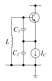 Figure 2: Simple common collector Colpitts oscillator (with simplified biasing) |
The Colpitts circuit, like other LC oscillators, consists of a gain device (such as a bipolar junction transistor, field effect transistor, operational amplifier, or vacuum tube) with its output connected to its input in a feedback loop containing a parallel LC circuit (tuned circuit) which functions as a bandpass filter to set the frequency of oscillation.
A Colpitts oscillator is the electrical dual of a Hartley oscillator, where the feedback signal is taken from an "inductive" voltage divider consisting of two coils in series (or a tapped coil). Fig. 1 shows the common-base Colpitts circuit. L and the series combination of C1 and C2 form the parallel resonant tank circuit which determines the frequency of the oscillator. The voltage across C2 is applied to the base-emitter junction of the transistor, as feedback to create oscillations. Fig. 2 shows the common-collector version. Here the voltage across C1 provides feedback. The frequency of oscillation is approximately the resonant frequency of the LC circuit, which is the series combination of the two capacitors in parallel with the inductor

The actual frequency of oscillation will be slightly lower due to junction capacitances and resistive loading of the transistor.
As with any oscillator, the amplification of the active component should be marginally larger than the attenuation of the capacitive voltage divider, to obtain stable operation. Thus, a Colpitts oscillator used as a variable frequency oscillator (VFO) performs best when a variable inductance is used for tuning, as opposed to tuning one of the two capacitors. If tuning by variable capacitor is needed, it should be done via a third capacitor connected in parallel to the inductor (or in series as in the Clapp oscillator).
Practical example

Fig. 3 shows a working example with component values. Instead of bipolar junction transistors, other active components such as field effect transistors or vacuum tubes, capable of producing gain at the desired frequency, could be used.
The capacitor at the base provides an AC path to ground for parasitic inductances that could lead to unwanted resonance at undesired frequencies.[6] Selection of the base's biasing resistors is not trivial. Periodic oscillation starts for a critical bias current and with the variation of the bias current to a higher value chaotic oscillations are observed.[7]
Theory

One method of oscillator analysis is to determine the input impedance of an input port neglecting any reactive components. If the impedance yields a negative resistance term, oscillation is possible. This method will be used here to determine conditions of oscillation and the frequency of oscillation.
An ideal model is shown to the right. This configuration models the common collector circuit in the section above. For initial analysis, parasitic elements and device non-linearities will be ignored. These terms can be included later in a more rigorous analysis. Even with these approximations, acceptable comparison with experimental results is possible.
Ignoring the inductor, the input impedance at the base can be written as

Where is the input voltage and is the input current. The voltage is given by


Where is the impedance of . The current flowing into is , which is the sum of two currents:


Where is the current supplied by the transistor. is a dependent current source given by


Where is the transconductance of the transistor. The input current is given by


Where is the impedance of . Solving for and substituting above yields


The input impedance appears as the two capacitors in series with an interesting term, which is proportional to the product of the two impedances:


If and are complex and of the same sign, will be a negative resistance. If the impedances for and are substituted, is

If an inductor is connected to the input, the circuit will oscillate if the magnitude of the negative resistance is greater than the resistance of the inductor and any stray elements. The frequency of oscillation is as given in the previous section.
For the example oscillator above, the emitter current is roughly 1 mA. The transconductance is roughly 40 mS. Given all other values, the input resistance is roughly

This value should be sufficient to overcome any positive resistance in the circuit. By inspection, oscillation is more likely for larger values of transconductance and smaller values of capacitance. A more complicated analysis of the common-base oscillator reveals that a low frequency amplifier voltage gain must be at least four to achieve oscillation.[8] The low frequency gain is given by:


If the two capacitors are replaced by inductors and magnetic coupling is ignored, the circuit becomes a Hartley oscillator. In that case, the input impedance is the sum of the two inductors and a negative resistance given by:

In the Hartley circuit, oscillation is more likely for larger values of transconductance and larger values of inductance.
Interestingly, the above analysis also describes the behavior of the Pierce oscillator. The Pierce oscillator, with two capacitors and one inductor, is equivalent to the Colpitts oscillator.[9] Equivalence can be shown by choosing the junction of the two capacitors as the ground point. An electrical dual of the standard Pierce oscillator using two inductors and one capacitor is equivalent to the Hartley oscillator.
Oscillation amplitude
The amplitude of oscillation is generally difficult to predict, but it can often be accurately estimated using the describing function method.
For the common-base oscillator in Figure 1, this approach applied to a simplified model predicts an output (collector) voltage amplitude given by:[10]

where is the bias current, and is the load resistance at the collector.


This assumes that the transistor does not saturate, the collector current flows in narrow pulses, and that the output voltage is sinusoidal (low distortion).
This approximate result also applies to oscillators employing different active device, such as MOSFETs and vacuum tubes.
References
- ↑ US 1624537, Colpitts, Edwin H., "Oscillation generator", published 1 February 1918, issued 12 April 1927
- ↑ Gottlieb, Irving Gottlieb (1997). Practical Oscillator Handbook. US: Elsevier. p. 151. ISBN 0750631023.
- ↑ Carr, Joe (2002). RF Components and Circuits. US: Newnes. p. 127. ISBN 0750648449.
- ↑ Basak, A. (1991). Analogue Electronic Circuits and Systems. UK: Cambridge University Press. p. 153. ISBN 0521360463.
- ↑ Rohde, Ulrich L.; Matthias Rudolph (2012). RF / Microwave Circuit Design for Wireless Applications, 2nd Ed. John Wiley & Sons. pp. 745–746. ISBN 1118431405.
- ↑ University of California Santa Barbara Untitled Publication, p. 3.
- ↑ S. Sarkar, S. Sarkar, B. C. Sarkar. "Nonlinear Dynamics of a BJT Based Colpitts Oscillator with Tunable Bias Current". IJEAT ISSN 2249-8958, Volume-2, Issue-5, June 2013. p. 1.
- ↑ Razavi, B. Design of Analog CMOS Integrated Circuits. McGraw-Hill. 2001.
- ↑ Theron Jones. "Design a Crystal Oscillator to Match Your Application". Maxim tutorial 5265 Sep 18, 2012, Maxim Integrated Products, Inc
- ↑ Trade-Offs in Analog Circuit Design: The Designer's Companion, Part 1 By Chris Toumazou, George S. Moschytz, Barrie Gilbert
Further reading
- Lee, T. The Design of CMOS Radio-Frequency Integrated Circuits. Cambridge University Press. 2004.
- Ulrich L. Rohde, Ajay K. Poddar, Georg Böck "The Design of Modern Microwave Oscillators for Wireless Applications ", John Wiley & Sons, New York, NY, May, 2005, ISBN 0-471-72342-8.
- George Vendelin, Anthony M. Pavio, Ulrich L. Rohde " Microwave Circuit Design Using Linear and Nonlinear Techniques ", John Wiley & Sons, New York, NY, May, 2005, ISBN 0-471-41479-4.
- Ulrich L. Rohde, Anisha M. Apte http://ieeexplore.ieee.org/document/7506417/ Everything You Always Wanted to Know About Colpitts Oscillators [Applications Note]
- Anisha M. Apte; Ajay K. Poddar; Ulrich L. Rohde; Enrico Rubiola, Colpitts oscillator: A new criterion of energy saving for high performance signal sources 2016 IEEE International Frequency Control Symposium (IFCS)
External links
- Java Simulation of a Colpitts oscillator
- Hemanshu R. Pota "Analysis of Common-Collector Colpitts Oscillator", 2005.