Double-sideband suppressed-carrier transmission
Double-sideband suppressed-carrier transmission (DSB-SC) is transmission in which frequencies produced by amplitude modulation (AM) are symmetrically spaced above and below the carrier frequency and the carrier level is reduced to the lowest practical level, ideally being completely suppressed.
In the DSB-SC modulation, unlike in AM, the wave carrier is not transmitted; thus, much of the power is distributed between the sidebands, which implies an increase of the cover in DSB-SC, compared to AM, for the same power used.
DSB-SC transmission is a special case of double-sideband reduced carrier transmission. It is used for radio data systems.
Spectrum
DSB-SC is basically an amplitude modulation wave without the carrier, therefore reducing power waste, giving it a 50% efficiency. This is an increase compared to normal AM transmission (DSB), which has a maximum efficiency of 33.333%, since 2/3 of the power is in the carrier which carries no intelligence, and each sideband carries the same information. Single Side Band (SSB) Suppressed Carrier is 100% efficient.
Spectrum plot of a DSB-SC signal:

Generation
DSB-SC is generated by a mixer. This consists of a message signal multiplied by a carrier signal. The mathematical representation of this process is shown below, where the product-to-sum trigonometric identity is used.
![\underbrace {V_{m}\cos \left(\omega _{m}t\right)}_{{{\mbox{Message}}}}\times \underbrace {V_{c}\cos \left(\omega _{c}t\right)}_{{{\mbox{Carrier}}}}=\underbrace {{\frac {V_{m}V_{c}}{2}}\left[\cos \left(\left(\omega _{m}+\omega _{c}\right)t\right)+\cos \left(\left(\omega _{m}-\omega _{c}\right)t\right)\right]}_{{{\mbox{Modulated Signal}}}}](../I/m/5a5b5ee2d07469277f5a570da3cda5e9ceec01d3.svg)

Demodulation
Demodulation is done by multiplying the DSB-SC signal with the carrier signal just like the modulation process. This resultant signal is then passed through a low pass filter to produce a scaled version of original message signal. DSB-SC can be demodulated by a simple envelope detector, like AM, if the modulation index is less than unity. Full depth modulation requires carrier re-insertion.
![\overbrace {{\frac {V_{m}V_{c}}{2}}\left[\cos \left(\left(\omega _{m}+\omega _{c}\right)t\right)+\cos \left(\left(\omega _{m}-\omega _{c}\right)t\right)\right]}^{{{\mbox{Modulated Signal}}}}\times \overbrace {V'_{c}\cos \left(\omega _{c}t\right)}^{{{\mbox{Carrier}}}}](../I/m/10be70e8c2bd5a09722075f8cb9d8dff864915c7.svg)
![= \left(\frac{1}{2}V_c V'_c\right)\underbrace{V_m \cos(\omega_m t)}_{\text{original message}} + \frac{1}{4}V_c V'_c V_m \left[\cos((\omega_m + 2\omega_c)t) + \cos((\omega_m - 2\omega_c)t)\right]](../I/m/2c094a8f49326dd035e8fd8d0d8519b627f2d371.svg)
The equation above shows that by multiplying the modulated signal by the carrier signal, the result is a scaled version of the original message signal plus a second term. Since , this second term is much higher in frequency than the original message. Once this signal passes through a low pass filter, the higher frequency component is removed, leaving just the original message.

Distortion and attenuation
For demodulation, the demodulation oscillator's frequency and phase must be exactly the same as modulation oscillator's, otherwise, distortion and/or attenuation will occur.
To see this effect, take the following conditions:
- Message signal to be transmitted:
- Modulation (carrier) signal:
- Demodulation signal (with small frequency and phase deviations from the modulation signal):


![V'_{c}\cos \left[(\omega _{c}+\Delta \omega )t+\theta \right]](../I/m/12d890390bf7ee207d27ce00328ec2150468c1ee.svg)
The resultant signal can then be given by
![f(t)\times V_{c}\cos(\omega _{c}t)\times V'_{c}\cos \left[(\omega _{c}+\Delta \omega )t+\theta \right]](../I/m/a3c390fda8004f4fa5683a61c7ad3d5e2e202532.svg)
![={\frac {1}{2}}V_{c}V'_{c}f(t)\cos \left(\Delta \omega \cdot t+\theta \right)+{\frac {1}{2}}V_{c}V'_{c}f(t)\cos \left[(2\omega _{c}+\Delta \omega )t+\theta \right]](../I/m/6a68b86960df0e291487bbfb0350006a07bb212c.svg)

The terms results in distortion and attenuation of the original message signal. In particular, if the frequencies are correct, but the phase is wrong, contribution from is a constant attenuation factor, also represents a cyclic inversion of the recovered signal, which is a serious form of distortion.


How it works
This is best shown graphically. Below is a message signal that one may wish to modulate onto a carrier, consisting of a couple of sinusoidal components.
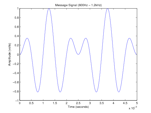
The equation for this message signal is .

The carrier, in this case, is a plain 5 kHz () sinusoid—pictured below.

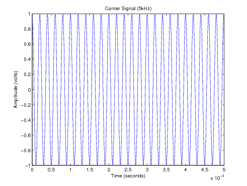
The modulation is performed by multiplication in the time domain, which yields a 5 kHz carrier signal, whose amplitude varies in the same manner as the message signal.

![x(t)=\underbrace {\cos \left(2\pi 5000t\right)}_{{\mbox{Carrier}}}\times \underbrace {\left[{\frac {1}{2}}\cos \left(2\pi 800t\right)-{\frac {1}{2}}\cos \left(2\pi 1200t\right)\right]}_{{\mbox{Message Signal}}}](../I/m/c908bd48c94a484e5cb06c3bf2fa72a3c3e473f3.svg)
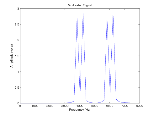
The name "suppressed carrier" comes about because the carrier signal component is suppressed—it does not appear in the output signal. This is apparent when the spectrum of the output signal is viewed:
References
![]() This article incorporates public domain material from the General Services Administration document "Federal Standard 1037C" (in support of MIL-STD-188).
This article incorporates public domain material from the General Services Administration document "Federal Standard 1037C" (in support of MIL-STD-188).
External links
- A DSBSC generation and demodulation instrument is described as side application of a commercial lock-in amplifier in Double-sideband Suppressed-carrier Modulation.