Filter (signal processing)
In signal processing, a filter is a device or process that removes some unwanted components or features from a signal. Filtering is a class of signal processing, the defining feature of filters being the complete or partial suppression of some aspect of the signal. Most often, this means removing some frequencies and not others in order to suppress interfering signals and reduce background noise. However, filters do not exclusively act in the frequency domain; especially in the field of image processing many other targets for filtering exist. Correlations can be removed for certain frequency components and not for others without having to act in the frequency domain.
There are many different bases of classifying filters and these overlap in many different ways; there is no simple hierarchical classification. Filters may be:
- linear or non-linear
- time-invariant or time-variant, also known as shift invariance. If the filter operates in a spatial domain then the characterization is space invariance.
- causal or not-causal: A filter is non-causal if its present output depends on future input. Filters processing time-domain signals in real-time must be causal, but not filters acting on spatial domain signals or deferred-time processing of time-domain signals.
- analog or digital
- discrete-time (sampled) or continuous-time
- passive or active type of continuous-time filter
- infinite impulse response (IIR) or finite impulse response (FIR) type of discrete-time or digital filter.
Linear continuous-time filters
Linear continuous-time circuit is perhaps the most common meaning for filter in the signal processing world, and simply "filter" is often taken to be synonymous. These circuits are generally designed to remove certain frequencies and allow others to pass. Circuits that perform this function are generally linear in their response, or at least approximately so. Any nonlinearity would potentially result in the output signal containing frequency components not present in the input signal.
The modern design methodology for linear continuous-time filters is called network synthesis. Some important filter families designed in this way are:
- Chebyshev filter, has the best approximation to the ideal response of any filter for a specified order and ripple.
- Butterworth filter, has a maximally flat frequency response.
- Bessel filter, has a maximally flat phase delay.
- Elliptic filter, has the steepest cutoff of any filter for a specified order and ripple.
The difference between these filter families is that they all use a different polynomial function to approximate to the ideal filter response. This results in each having a different transfer function.
Another older, less-used methodology is the image parameter method. Filters designed by this methodology are archaically called "wave filters". Some important filters designed by this method are:
- Constant k filter, the original and simplest form of wave filter.
- m-derived filter, a modification of the constant k with improved cutoff steepness and impedance matching.
Terminology
Some terms used to describe and classify linear filters:
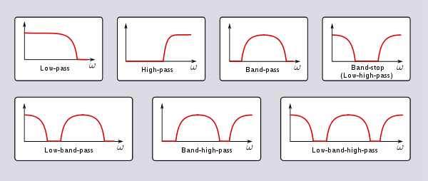
- The frequency response can be classified into a number of different bandforms describing which frequency bands the filter passes (the passband) and which it rejects (the stopband):
- Low-pass filter – low frequencies are passed, high frequencies are attenuated.
- High-pass filter – high frequencies are passed, low frequencies are attenuated.
- Band-pass filter – only frequencies in a frequency band are passed.
- Band-stop filter or band-reject filter – only frequencies in a frequency band are attenuated.
- Notch filter – rejects just one specific frequency - an extreme band-stop filter.
- Comb filter – has multiple regularly spaced narrow passbands giving the bandform the appearance of a comb.
- All-pass filter – all frequencies are passed, but the phase of the output is modified.
- Cutoff frequency is the frequency beyond which the filter will not pass signals. It is usually measured at a specific attenuation such as 3 dB.
- Roll-off is the rate at which attenuation increases beyond the cut-off frequency.
- Transition band, the (usually narrow) band of frequencies between a passband and stopband.
- Ripple is the variation of the filter's insertion loss in the passband.
- The order of a filter is the degree of the approximating polynomial and in passive filters corresponds to the number of elements required to build it. Increasing order increases roll-off and brings the filter closer to the ideal response.
One important application of filters is in telecommunication. Many telecommunication systems use frequency-division multiplexing, where the system designers divide a wide frequency band into many narrower frequency bands called "slots" or "channels", and each stream of information is allocated one of those channels. The people who design the filters at each transmitter and each receiver try to balance passing the desired signal through as accurately as possible, keeping interference to and from other cooperating transmitters and noise sources outside the system as low as possible, at reasonable cost.
Multilevel and multiphase digital modulation systems require filters that have flat phase delay—are linear phase in the passband—to preserve pulse integrity in the time domain,[1] giving less intersymbol interference than other kinds of filters.
On the other hand, analog audio systems using analog transmission can tolerate much larger ripples in phase delay, and so designers of such systems often deliberately sacrifice linear phase to get filters that are better in other ways—better stop-band rejection, lower passband amplitude ripple, lower cost, etc.
Technologies
Filters can be built in a number of different technologies. The same transfer function can be realised in several different ways, that is the mathematical properties of the filter are the same but the physical properties are quite different. Often the components in different technologies are directly analogous to each other and fulfill the same role in their respective filters. For instance, the resistors, inductors and capacitors of electronics correspond respectively to dampers, masses and springs in mechanics. Likewise, there are corresponding components in distributed element filters.
- Electronic filters were originally entirely passive consisting of resistance, inductance and capacitance. Active technology makes design easier and opens up new possibilities in filter specifications.
- Digital filters operate on signals represented in digital form. The essence of a digital filter is that it directly implements a mathematical algorithm, corresponding to the desired filter transfer function, in its programming or microcode.
- Mechanical filters are built out of mechanical components. In the vast majority of cases they are used to process an electronic signal and transducers are provided to convert this to and from a mechanical vibration. However, examples do exist of filters that have been designed for operation entirely in the mechanical domain.
- Distributed element filters are constructed out of components made from small pieces of transmission line or other distributed elements. There are structures in distributed element filters that directly correspond to the lumped elements of electronic filters, and others that are unique to this class of technology.
- Waveguide filters consist of waveguide components or components inserted in the waveguide. Waveguides are a class of transmission line and many structures of distributed element filters, for instance the stub (electronics), can also be implemented in waveguides.
- Crystal filters use quartz crystals as resonators, or some other piezoelectric material.
- Acoustic filters
- Optical filters were originally developed for purposes other than signal processing such as lighting and photography. With the rise of optical fiber technology, however, optical filters increasingly find signal processing applications and signal processing filter terminology, such as longpass and shortpass, are entering the field.
The transfer function
The transfer function of a filter is most often defined in the domain of the complex frequencies. The back and forth passage to/from this domain is operated by the Laplace transform and its inverse (therefore, here below, the term "input signal" shall be understood as "the Laplace transform of" (the time representation of) the input signal, and so on).
The transfer function of a filter is the ratio of the output signal to that of the input signal as a function of the complex frequency :


with .

The transfer function of all linear time-invariant filters generally share certain characteristics:
- For filters which are constructed of discrete components, their transfer function must be the ratio of two polynomials in , i.e. a rational function of . The order of the transfer function will be the highest power of encountered in either the numerator or the denominator.
- The polynomials of the transfer function will all have real coefficients. Therefore, the poles and zeroes of the transfer function will either be real or occur in complex conjugate pairs.
- Since the filters are assumed to be stable, the real part of all poles (i.e. zeroes of the denominator) will be negative, i.e. they will lie in the left half-plane in complex frequency space.
Distributed element filters do not, in general, produce rational functions but can often approximate to them.
The proper construction of a transfer function involves the Laplace transform, and therefore it is needed to assume null initial conditions, because

And when f(0)=0 we can get rid of the constants and use the usual expression

An alternative to transfer functions is to give the behavior of the filter as a convolution. The convolution theorem, which holds for Laplace transforms, guarantees equivalence with transfer functions.
Classification
Filters may be specified by family and bandform. A filter's family is specified by the approximating polynomial used and each leads to certain characteristics of the transfer function of the filter. Some common filter families and their particular characteristics are:
- Butterworth filter – no gain ripple in pass band and stop band, slow cutoff
- Chebyshev filter (Type I) – no gain ripple in stop band, moderate cutoff
- Chebyshev filter (Type II) – no gain ripple in pass band, moderate cutoff
- Bessel filter – no group delay ripple, no gain ripple in both bands, slow gain cutoff
- Elliptic filter – gain ripple in pass and stop band, fast cutoff
- Optimum "L" filter
- Gaussian filter – no ripple in response to step function
- Hourglass filter
- Raised-cosine filter
Each family of filters can be specified to a particular order. The higher the order, the more the filter will approach the "ideal" filter; but also the longer the impulse response is and the longer the latency will be. An ideal filter has full transmission in the pass band, complete attenuation in the stop band, and an abrupt transition between the two bands, but this filter has infinite order (i.e., the response cannot be expressed as a linear differential equation with a finite sum) and infinite latency (i.e., its compact support in the Fourier transform forces its time response to be ever lasting).
Here is an image comparing Butterworth, Chebyshev, and elliptic filters. The filters in this illustration are all fifth-order low-pass filters. The particular implementation – analog or digital, passive or active – makes no difference; their output would be the same.
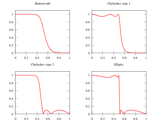
As is clear from the image, elliptic filters are sharper than all the others, but they show ripples on the whole bandwidth.
Any family can be used to implement a particular bandform of which frequencies are transmitted, and which, outside the passband, are more or less attenuated. The transfer function completely specifies the behavior of a linear filter, but not the particular technology used to implement it. In other words, there are a number of different ways of achieving a particular transfer function when designing a circuit. A particular bandform of filter can be obtained by transformation of a prototype filter of that family.
Impedance matching
Impedance matching structures invariably take on the form of a filter, that is, a network of non-dissipative elements. For instance, in a passive electronics implementation, it would likely take the form of a ladder topology of inductors and capacitors. The design of matching networks shares much in common with filters and the design invariably will have a filtering action as an incidental consequence. Although the prime purpose of a matching network is not to filter, it is often the case that both functions are combined in the same circuit. The need for impedance matching does not arise while signals are in the digital domain.
Similar comments can be made regarding power dividers and directional couplers. When implemented in a distributed element format, these devices can take the form of a distributed element filter. There are four ports to be matched and widening the bandwidth requires filter-like structures to achieve this. The inverse is also true: distributed element filters can take the form of coupled lines.
Some filters for specific purposes
- Audio filter
- Line filter
- Scaled correlation, high-pass filter for correlations
- Texture filtering
Filters for removing noise from data
See also
References
- ↑ Richard Markell. '"Better than Bessel" Linear Phase Filters for Data Communications'. 1994. p. 3.
- Miroslav D. Lutovac, Dejan V. Tošić, Brian Lawrence Evans, Filter Design for Signal Processing Using MATLAB and Mathematica, Miroslav Lutovac, 2001 ISBN 0201361302.
- B. A. Shenoi, Introduction to Digital Signal Processing and Filter Design, John Wiley & Sons, 2005 ISBN 0471656380.
- L. D. Paarmann, Design and Analysis of Analog Filters: A Signal Processing Perspective, Springer, 2001 ISBN 0792373731.
- J.S.Chitode, Digital Signal Processing, Technical Publications, 2009 ISBN 8184316461.
- Leland B. Jackson, Digital Filters and Signal Processing, Springer, 1996 ISBN 079239559X.