Fire alarm control panel

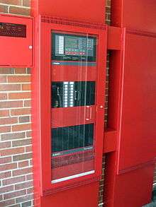
A Fire Alarm Control Panel (FACP), or Fire Alarm Control Unit (FACU), is the controlling component of a Fire Alarm System. The panel receives information from environmental sensors designed to detect changes associated with fire, monitors their operational integrity and provides for automatic control of equipment, and transmission of information necessary to prepare the facility for fire based on a predetermined sequence. The panel may also supply electrical energy to operate any associated sensor, control, transmitter, or relay. There are four basic types of panels: coded panels, conventional panels, addressable panels, and multiplex systems.
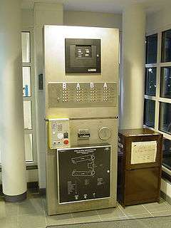
Coded
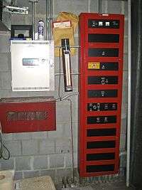
Coded panels were the earliest type of central fire alarm control, and were made during the 1800s to the 1970s. A coded panel is similar in many ways to a modern conventional panel (described below), except each zone was connected to its own code wheel ( i.e. An alarm in zone 1 would sound code 1-2-4 [through the bells or horns in the building], while zone 2 would sound 1-2-5), which, depending on the way the panel was set up, would either do sets of four rounds of code until the initiating pull station was reset (similar to a coded pull station) or run continuously until the panel itself was reset. Large panels could take up an entire wall in a mechanical room, with dozens of code wheels. Lists of codes had to be maintained, sometimes with copies posted above pull stations (this setup is commonly seen in older wings of hospitals). Smaller panels could be set up in one of two ways. Most of the time, the panel would only have one zone, and therefore, only one code. Common one-zone codes were 4-4-0 and 17-0-0 (which is similar to the 120 bpm March Time setting used on later panels, which has in turn been replaced with an interrupted four count uniform temporal code 3 pattern used since 1996). Alternatively, the panel could be made with no code wheels, using only what was called the gong relay. Normally, this would be used in a system with coded pull stations to re-transmit the coding strikes from the pulls. However, it could also be used as its own zone, with the connected horns or bells sounding continuously instead of in a particular code. These panels are not common today, but can sometimes be found in older buildings such as those on college campuses or hospitals.
Today, there are two types of fire panels:
- Conventional fire alarm panel;
- Addressable fire alarm panel
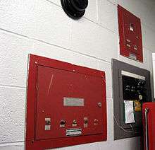
Conventional
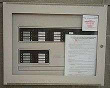

Conventional panels have been around ever since electronics became small enough to make them viable. Conventional panels are used less frequently in large buildings than in the past, but are not uncommon on smaller projects such as small schools, stores, restaurants, and apartments.
A conventional Fire Alarm Control Panel employs one or more circuits, connected to sensors (initiating devices) wired in parallel. These sensors are devised to dramatically decrease the circuit resistance when the environmental influence on any sensor exceeds a predetermined threshold. In a conventional fire alarm system, the information density is limited to the number of such circuits used.
To facilitate location and control of fire within a building, the structure is subdivided into definite areas or zones. Floors of a multistory building are one type of zone boundary.
An Initiating Device Circuit connected to multiple devices within the same "zone" of protection, effectively provides 2 bits of information about the zone corollary to the state of the circuit; normal, or off normal and alarm or quiescent. The state of each Initiating Device Circuit within a zone displays at the Fire Alarm Control Panel using visible indications called Annunciators.
These Annunciators may employ a graphical representation of the Zone boundaries on a floor plan (Zone map) using textual descriptions, illuminated icons, illuminated sections, or illuminated points on the map corresponding to Initiating Circuits connected to the Fire Alarm Control Panel.
For this reason, slang often inaccurately refers to initiating circuits of a Fire Alarm Control Panel as Zones.
Larger systems and increasing demand for finer diagnostic detail beyond broad area location and control functions expanded the control by Zone strategy of conventional systems by providing multiple initiating circuits within a common Zone, each exclusively connected to a particular type of initiating device, or group of devices. This arrangement forms a device type by Zone matrix whose information is particularly suited to the Tabular Annunciator In multistorey buildings employing a Tabular Annunciator for Example; rows of indicators define the floors horizontally in their stacked relationship and the type of device installed on that floor displays as columns of indicators vertically aligned through each floor. The intersection of the floor and device indicators provides the combined information. The density of information however remains a function of the number of circuits employed.
Even larger systems and demands for finer diagnostic and location detail led to the introduction of addressable fire alarm systems with each addressable device providing specific information about its state while sharing a common communication circuit. Annunciation and location strategies for the most part remain relatively unchanged.

Multiplex systems
Multiplex systems, a sort of transition between conventional and modern addressable systems, were often used in large buildings and complexes from the mid to late 1970s into the late 1980s. Early on, these systems were programmed to function as large conventional systems. Gradually, later installations began to feature components and features of modern addressable systems. These systems were often capable of controlling more than a building's fire alarm system (i.e. HVAC, security, electronic door locks...) without any type of alarm or trouble condition present. While the main panel was the brains of the system and could be used to access certain functions, fire alarm controls were usually accessed through transponders. These were smaller conventional panels programmed to 'communicate' the status of part of the system to the main panel and also could be used to access basic fire alarm control functions.
Releasing panels
Releasing panels are capable of using solenoids to disperse fire-fighting chemical agents such as halon or water from piping located throughout a building. A releasing panel usually will have a manual abort switch to abort an accidental release which could damage property or equipment. Releasing capability can be part of both addressable or conventional panels.
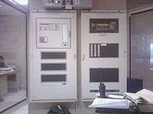
Addressable
Addressable panels are usually more advanced than their conventional counterparts, with greater information capacity and control flexibility. Addressable fire alarm panels were introduced by many manufacturers during the microcontroller boom in the mid 1980s.
Signaling Line Circuits
Addressable Fire Alarm Control Panel employ one or more Signaling Line Circuits - usually referred to as loops or SLC loops - ranging between one and thirty. Depending on the protocol used, a Signaling Line Circuit can monitor and control several hundred devices. Some protocols permit any mix of detectors and input/output modules, while other protocols have 50% of channel capacity restricted to detectors/sensors and 50% restricted to input/output modules. Each SLC polls the devices connected, which can number from a few devices to several hundred, depending on the manufacturer. Large systems may have multiple Signaling Line Circuits.[1][2]
Each device on a SLC has its own address, and so the panel knows the state of each individual device connected to it. Common addressable input (initiating) devices include
- Smoke detectors
- Heat Detectors (Rate of Rise and Fixed Temperature)
- Manual call points or manual pull stations
- Notification appliances
- Responders
- Fire sprinkler system inputs
- Switches
- Flow control
- Pressure
- Isolate
- Standard switches
Addressable output devices are known as relays and include
- (Warning System/Bell) Relays
- Door Holder Relays
- Auxiliary (Control Function) Relays
Relays are used to control a variety of functions such as
- Switching fans on or off
- Closing/opening doors
- Activating fire suppression systems
- Activating notification appliances
- Shutting down industrial equipment
- Recalling elevators to a safe exit floor
- Activating another fire alarm panel or communicator
Mapping
Also known as "cause and effect" or "programming", mapping is the process of activating outputs depending on which inputs have been activated. Traditionally, when an input device is activated, a certain output device (or relay) is activated. As time has progressed, more and more advanced techniques have become available, often with large variations in style between different companies.
Zones
Zones are usually made by dividing a building, or area into different sections. Then depending on the specific zone, a certain amount and type of device is added to the zone to perform its given job.
Groups
Groups contain multiple output devices such as relays. This allows a single input, such as a smoke detector or MCP, to have only one output programmed to a group, which then maps to between two and many outputs or relays. This enables an installer to simplify programming by having many inputs map to the same outputs, and be able to change them all at once, and also allows mapping to more outputs than the programming space for a single detector/input allows.
Boolean logic
This is the part of a fire panel that has the largest variation between different panels. It allows a panel to be programmed to implement fairly complex inputs. For instance, a panel could be programmed to notify the fire department only if more than one device has activated. It can also be used for staged evacuation procedures in conjunction with timers.
Networking
The principle of networking involves connecting several panels together to form a system. Inputs on one panel may activate outputs on another, for example, or the network may allow monitoring of many systems. Networking is often used in situations where one panel is not large enough, or in multiple-building situations. Networking is also an effective way to decouple systems to reduce the risk of a large portion of a facility going offline at any time due to system failure or maintenance requirements. Sub-Networks can be created using either hardware or software architectures. Networked systems normally are more costly and involve additional training and system configuration for successful implementation.
Although quasi-standards exist that allow panels from different manufacturers to be networked with each other, they are not in favor with a lot of companies. One of the most common protocols used is BACnet which is common for various type of industrial networks. At least one system manufacturer, The Mircom Group of Companies provides a networkable Fire Alarm Control Panel with a BACnet inteface allowing non-proprietary interoperability of the Fire Alarm Control Panel FACP with other building systems. Typical interconnected systems to the Fire Alarm Control Panel include HVAC, Building Automation Controllers, Security/Access Control or Elevator Controllers. Interoperable systems greatly reduce the long term maintenance cost of a system and can provide greater emergency response than proprietary offerings.[3]
The Arcnet protocol has been used for years in industrial applications and it is also used for networking Fire Alarm Control Panels.
More recently, some panels are being networked with standard Ethernet, but this is not yet very common. Most organizations choose to create their own proprietary protocol, which has the added benefit of allowing them to do anything they like, allowing the technology to progress further. However, a bridging layer between the proprietary network and BACnet is usually available.
Networking may be used to allow a number of different panels to be monitored by one graphical monitoring system.
Monitoring
In nearly every state in the USA, the International Building Code requires fire alarm and sprinkler systems to be monitored by an approved supervising station.
A fire alarm system consists of a computer-based control connected to a central station. The majority of fire alarm systems installed in the USA are monitored by a UL listed or FM Global approved supervising station.
These systems will generally have a top level map of the entire site, with various building levels displayed. The user (most likely a security guard) can progress through the different stages. From top level site → building plan → floor plan → zone plan, or however else the building's security system is organised.
A lot of these systems have touch screens, but most users tend to prefer a mouse (and a normal monitor), as it is quite easy for a touch screen to become misaligned and for mistakes to be made. With the advent of the optical mouse, this is now a very viable option.
System functions
There are many functions on a fire alarm panel. Some of these are:
Class change
This button, or input terminals connected to an external timeswitch, will sound the notification appliances briefly in a different cadence. It is used to signify class change / lesson breaks in schools, and allows the fire alarm system to be used instead of a separate class bell system. This ensures pupils are familiar with the sound of the alarm and means the notification appliance circuits are tested several times a day.
System reset
This resets the panel after an alarm condition. All initiating devices are reset, and the panel is cleared of any alarm conditions. If an initiating device is still in alarm after the system is reset, such as a smoke detector continuing to sense smoke or a manual pull station still in an activated position, another alarm will be initiated. A system reset is often required to clear supervisory conditions. A system reset does not usually clear trouble conditions. Most trouble conditions will clear automatically when conditions are returned to normal.
On the UK and most US panels, a "Silence" or "Acknowledge" is usually required before a "System Reset" can be performed.
Acknowledge
This function also abbreviated to "ACK", is used to acknowledge an abnormal situation such as an alarm, trouble or supervisory.
Drill
Also known as "manual evacuation" or "evacuate". On panels that have this function, the drill function activates the system's notification appliances, often for purposes of conducting a fire drill. Using the drill function, an alarm is normally not transmitted to the fire department or monitoring center. However, building personnel often notify these agencies in advance in case an alarm is inadvertently transmitted.
Signal silence
Also known as "alarm silence" or "audible silence". Depending on the configuration of the alarm system, this function will either silence the system's notification appliances completely or will silence only the audible alarm, while strobe lights continue to flash. Audible silence allows for easier communication amongst emergency responders while responding to an alarm. This can also be used during construction as a means of a preliminary test, before the final full test. This is very effective.
Lamp test
Also known as "flash test". This button is known to have become obsolete but is still used on many panels. This function is used to check the condition of the LEDs themselves. A "Lamp Test" button is required by code on multi-zone panels installed in Canada. Many panels do a lamp test when the system is reset.
Walk Test
"Walk Test" is a method of testing many fire alarm devices that saves time and requires fewer technicians at the location. Using "Walk Test", A Technician Can simply walk around the building and initiate any device he/she would like. Doing so will send a signal to the panel, which will pulse the NAC a certain amount of times to indicate the zone on which the device is wired to. Silent Walktest will only flash the alarm light on the panel, thus not disturbing what is happening in the building.
Panel alerting
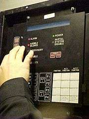
Many panels today have the capability of alerting building personnel of a situation which can arise into a potentially serious problem. Fire alarm panels indicate an abnormal condition via a solid or flashing LED. Some panels also contain a small sounder, used in conjunction with the visual alert. A number of indicators are shown below. Note that not all fire alarm panels have all of these indicators.
Alarm
Also known as "Fire" or "General Alarm". This indicator is lit when an alarm condition exists in the system, initiated by smoke detectors, heat detectors, sprinkler flow switches, manual pull stations, manual call points, or otherwise. Along with the indicator on the panel, notification appliances, such as horns and strobes, are also activated, signaling a need to evacuate to building occupants. In an alarm condition, the fire alarm panel indicates where the alarm originated. The alarm panel can be reset once the device which initiated the alarm is reset, such as returning the handle of a manual pull station to its normal position.
Audible silence
The Audible Silence indicator is used in conjunction with the "Alarm" indicator. It indicates that the fire alarm panel is still in an alarm condition, but that notification appliances have been silenced. While the alarm is silenced, other functions in an alarm condition continue to operate, such as emergency service for elevators, stairway pressurization, and ventilation functions. A new alarm initiation while the alarm is silenced will take the panel out of Audible Silence and reactivate the notification appliances.
Drill
Also known as "Manual Evacuation" or "Evacuate". On panels containing this function, the "Drill" indicator shows that the alarm condition was activated from the fire alarm panel, often in order to conduct a fire drill. When an alarm is initiated for a drill, the fire department or monitoring company is usually not notified automatically.
Prealarm
This LED is often used in conjunction with a two-stage system, in which the panel requires two devices to be activated (and/or a predetermined time limit to run out after one device is activated) in order to go into full alarm.[4] This is mostly used in areas where false alarms are a common problem, or in large applications (such as hospitals) where evacuating the entire building would not be efficient. The prealarm LED is lit when one device has tripped. The prealarm LED may also be used if an analog smoke detector registers low levels of smoke in the detection chamber, but not enough to trigger a full alarm.[5] Depending on the system's layout, the NAC's may or may not activate for prealarm conditions. In a two-stage system, the NAC's are typically coded to a special first-stage coding, or in some situations where a loud alarm signal could be disruptive, chimes will activate. If there is a voice evacuation system, it will usually instruct building occupants to await further instructions while the alarm is being investigated.
Priority 2 alarm
Also known as "Security". This LED can only activate if there is a secondary device hooked into the "Priority 2 Alarm" terminals. This secondary device could be a security system, building management system, or another fire alarm control panel. Depending on how the panel is programmed, the panel's alarms may or may not activate when a condition like this is present.
Trouble
Also known as "Fault" or "Defect". When held steady or flashing, it means that a trouble condition exists on the panel. Trouble conditions are often activated by a contaminated smoke detector or an electrical problem within the system. Trouble conditions are also activated by a zone being disabled (disconnected from the system), a circuit being disabled, low power on the backup battery, the disabling of a notification appliance, the ground faults, or short or open circuits. Usually the alarm panel's sounder will activate if a trouble condition exists, though older systems would sometimes activate a bell or other audible signal connected to the panel. In a trouble condition, the panel displays the zone or devices causing the condition. Usually, the "Trouble" indicator goes out automatically when the situation causing the trouble condition is rectified, however in some systems (EST) the panel must be reset to clear the trouble alarm. Some panels have more specific indicators such as 'Trouble-PSU' which shows when the panel itself is compromised and 'Trouble-Bell' ('Sounder fault' on UK panels) which shows that the sounders are not functioning correctly. On most panels, an acknowledge button is pressed to turn off the panel's buzzer.
Supervisory
This signal indicates that a portion of the building's fire protection system has been disabled (such as a fire sprinkler control valve being closed and, consequently, a sprinkler tamper switch being activated), or, less frequently, that a lower priority initiating device has been triggered (such as a duct smoke detector). Depending on the system's design, the supervisory point may be latching, meaning the panel must be reset to clear the supervisory condition, or non-latching, meaning the indicator automatically goes out when the condition has cleared. However, some panels require a reset regardless of whether the supervisory point is latching or non-latching.
AC power
Also known as "Normal". When this indicator is lit, power is being provided to the system from the building's electrical system, and not from the backup battery. When an AC power condition changes, the Trouble indicator comes on and the AC power indicator goes off and the screen alerts building personnel of a power failure. If the AC power indicator is lit without any other indicators also lit, then the system is in a normal condition. If no LEDs are lit, there is no power source feeding the panel.
DC power
This is used to tell the operator that DC power (batteries) are being charged or used. While using DC power, the system remains in a fault condition.
High rate
This LED is on when the battery charger is in the high rate charge state, in which the charger voltage is boosted to charge batteries faster after being depleted.
See also
- Fire protection
- Active fire protection
- Fire alarm
- EN 54 Fire detection and fire alarm systems,
- Burglar alarm
References
- ↑ "Fire Alarm Control Panel: MS9600/MS9600E" (PDF). Fire-Lite Alarms. 2003-07-09. Retrieved 2009-05-15.
|section=ignored (help) - ↑ "ZX5Se Multi-protocol Fire Alarm Control Panel" (PDF). Morley-IAS. 2003. Retrieved 2009-05-15. Archived March 21, 2012, at the Wayback Machine.
- ↑ "BACNet based Fire Alarm Control Panel". The Mircom Group of Companies.
- ↑ Mircom FA-1000 Fire Alarm Control Panel Specifications
- ↑ Wire-Free Protection Ltd.
| Wikimedia Commons has media related to Fire alarm control panels. |
.jpg)