Fluid bearing
Fluid bearings are bearings in which the load is supported by a thin layer of rapidly moving pressurized liquid or gas between the bearing surfaces.[1] Since there is no contact between the moving parts, there is no sliding friction, allowing fluid bearings to have lower friction, wear and vibration than many other types of bearings.[1]
They can be broadly classified into two types: fluid dynamic bearings and hydrostatic bearings. Hydrostatic bearings are externally pressurized fluid bearings, where the fluid is usually oil, water or air, and the pressurization is done by a pump. Hydrodynamic bearings rely on the high speed of the journal (the part of the shaft resting on the fluid) to pressurize the fluid in a wedge between the faces. Fluid bearings are frequently used in high load, high speed or high precision applications where ordinary ball bearings would have short life or cause high noise and vibration. They are also used increasingly to reduce cost. For example, hard disk drive motor fluid bearings are both quieter and cheaper than the ball bearings they replace.
The fluid bearing may have been invented by French civil engineer L. D. Girard, who in 1852 proposed a system of railway propulsion incorporating water-fed hydraulic bearings.[2][1]
Operation
Fluid bearings are noncontact bearings that use a thin layer of rapidly moving pressurized liquid or gas fluid between the moving bearing faces, typically sealed around or under the rotating shaft.[1] The moving parts do not come into contact, so there is no sliding friction; the load force is supported solely by the pressure of the moving fluid. There are two principal ways of getting the fluid into the bearing:
- In fluid static, hydrostatic and many gas or air bearings, the fluid is pumped in through an orifice or through a porous material. Such bearings should be equipped with the shaft position control system, which adjusts the fluid pressure and consumption according to the rotation speed and shaft load.[3]
- In fluid-dynamic bearings, the bearing rotation sucks the fluid on to the inner surface of the bearing, forming a lubricating wedge under or around the shaft.
Hydrostatic bearings rely on an external pump. The power required by that pump contributes to system energy loss, just as bearing friction otherwise would. Better seals can reduce leak rates and pumping power, but may increase friction.
Hydrodynamic bearings rely on bearing motion to suck fluid into the bearing, and may have high friction and short life at speeds lower than design, or during starts and stops. An external pump or secondary bearing may be used for startup and shutdown to prevent damage to the hydrodynamic bearing. A secondary bearing may have high friction and short operating life, but good overall service life if bearing starts and stops are infrequent.
Hydrodynamic lubrication
Hydrodynamic (HD) lubrication, also known as fluid film lubrication has essential elements:
- A lubricant, which must be a viscous fluid.
- Hydrodynamic flow behavior of fluid between bearing and journal.
- The surfaces between which the fluid films move must be convergent.
Hydrodynamic (Full Film) Lubrication is obtained when two mating surfaces are completely separated by a cohesive film of lubricant.
The thickness of the film thus exceeds the combined roughness of the surfaces. The coefficient of friction is lower than with boundary-layer lubrication. Hydrodynamic lubrication prevents wear in moving parts, and metal to metal contact is prevented.
Hydrodynamic lubrication requires thin, converging fluid films. These fluids can be liquid or gas, so long as they exhibit viscosity. In computer components, like a hard disk, heads are supported by hydrodynamic lubrication in which the fluid film is the atmosphere.
The scale of these films is on the order of micrometers. Their convergence creates pressures normal to the surfaces they contact, forcing them apart.
3 Types of bearings include:
- Self-acting: Film exists due to relative motion. e.g. spiral groove bearings.
- Squeeze film: Film exists due to relative normal motion.
- Externally pressurized: Film exists due to external pressurization.
Conceptually the bearings can be thought of as two major geometric classes: bearing-journal (anti-friction), and plane-slider (friction).
The Reynolds equations can be used to derive the governing principles for the fluids. Note that when gases are used, their derivation is much more involved.
The thin films can be thought to have pressure and viscous forces acting on them. Because there is a difference in velocity there will be a difference in the surface traction vectors. Because of mass conservation we can also assume an increase in pressure, making the body forces different.
- Hydrodynamic lubrication – characteristics:
- Fluid film at the point of minimum thickness decreases in thickness as the load increases
- Pressure within the fluid mass increases as the film thickness decreases due to load
- Pressure within the fluid mass is greatest at some point approaching minimum clearance and lowest at the point of maximum clearance (due to divergence)
- Viscosity increases as pressure increases (more resistance to shear)
- Film thickness at the point of minimum clearance increases with the use of more viscous fluids
- With same load, the pressure increases as the viscosity of fluid increases
- With a given load and fluid, the thickness of the film will increase as speed is increased
- Fluid friction increases as the viscosity of the lubricant becomes greater
- Hydrodynamic condition – Fluid velocity:
- Fluid velocity depends on velocity of the journal or rider
- Increase in relative velocity tends towards a decrease in eccentricity of journal bearing centers
- This is accompanied by greater minimum film thickness
- Hydrodynamic condition – Load:
- Increase in load decreases minimum film thickness
- Also increases pressure within the film mass to provide a counteracting force
- Pressure acts in all directions, hence it tends to squeeze the oil out of the ends of the bearing
- Increase in pressure increases fluid viscosity
- Bearing characteristic number:
Since viscosity, velocity, and load determine the characteristics of a hydrodynamic condition, a bearing characteristic number was developed based on the effects of these on film thickness.
- Increase in velocity increases min. film thickness
- Increase in viscosity increases min. film thickness
- Increase in load decreases min. film thickness
Therefore,
- Viscosity × velocity/unit load = a dimensionless number = C
C is known as the bearing characteristic number.
The value of C, to some extent, gives an indication of whether there will be hydrodynamic lubrication or not
Characteristics and principles of operation
Fluid bearings can be relatively cheap compared to other bearings with a similar load rating. The bearing can be as simple as two smooth surfaces with seals to keep in the working fluid. In contrast, a conventional rolling-element bearing may require many high-precision rollers with complicated shapes. Hydrostatic and many gas bearings do have the complication and expense of external pumps.
Most fluid bearings require little or no maintenance, and have almost unlimited life. Conventional rolling-element bearings usually have shorter life and require regular maintenance. Pumped hydrostatic and aerostatic (gas) bearing designs retain low friction down to zero speed and need not suffer start/stop wear, provided the pump does not fail.
Fluid bearings generally have very low friction—far better than mechanical bearings. One source of friction in a fluid bearing is the viscosity of the fluid. Hydrostatic gas bearings are among the lowest friction bearings. However, lower fluid viscosity also typically means fluid leaks faster from the bearing surfaces, thus requiring increased power for pumps or friction from seals.
When a roller or ball is heavily loaded, fluid bearings have clearances that change less under load (are "stiffer") than mechanical bearings. It might seem that bearing stiffness, as with maximum design load, would be a simple function of average fluid pressure and the bearing surface area. In practice, when bearing surfaces are pressed together, the fluid outflow is constricted. This significantly increases the pressure of the fluid between the bearing faces. As fluid bearing faces can be comparatively larger than rolling surfaces, even small fluid pressure differences cause large restoring forces, maintaining the gap.
However, in lightly loaded bearings, such as disk drives, the typical ball bearing stiffnesses are ~10^7 MN/m. Comparable fluid bearings have stiffness of ~10^6 MN/m. Because of this, some fluid bearings, particularly hydrostatic bearings, are deliberately designed to pre-load the bearing to increase the stiffness.
Fluid bearings often inherently add significant damping. This helps attenuate resonances at the gyroscopic frequencies of journal bearings (sometimes called conical or rocking modes).
It is very difficult to make a mechanical bearing which is atomically smooth and round; and mechanical bearings deform in high-speed operation due to centripetal force. In contrast, fluid bearings self-correct for minor imperfections.
Fluid bearings are typically quieter and smoother (more consistent friction) than rolling-element bearings. For example, hard disks manufactured with fluid bearings have noise ratings for bearings/motors on the order of 20–24 dB, which is a little more than the background noise of a quiet room. Drives based on rolling-element bearings are typically at least 4 dB noisier.
Fluid bearings can be made with a lower NRRO (non repeatable run out) than a ball or rolling element bearing. This can be critical in modern hard disk drive and ultra precision spindles.
Tilting pad bearings are used as radial bearings for supporting and locating shafts in compressors.
Disadvantages
- Overall power consumption is typically higher compared to ball bearings.
- Power consumption and stiffness or damping greatly vary with temperature, which complicates the design and operation of a fluid bearing in wide temperature range situations.
- Fluid bearings can catastrophically seize under shock situations. Ball bearings deteriorate more gradually and provide acoustic symptoms.
- Like cage frequency vibration in a ball bearing, the half frequency whirl is a bearing instability that generates eccentric precession which can lead to poor performance and reduced life.
- Fluid leakage; keeping fluid in the bearing can be a challenge.
- Oil fluid bearings are impractical in environments where oil leakage can be destructive or where maintenance is not economical.
- Fluid bearing "pads" often have to be used in pairs or triples to avoid the bearing tilting and losing the fluid from one side.
- Unlike greaseless mechanical bearings, fluid bearings cannot operate at the extremely low temperatures needed for some specialized scientific research applications.
Some fluid bearings
Foil bearings
Foil bearings are a type of fluid dynamic air bearing that was introduced in high speed turbine applications in the 1960s by Garrett AiResearch. They use a gas as the working fluid, usually air and require no external pressurisation system.
Journal bearings
Journal bearings are lubricated with fluid. The working part of the bearing operates by carrying oil at a low pressure and is compressed to allow the bearing to spin around the shaft without any contact.[4]
Air bearings
Unlike contact-roller bearings, an air bearing (or air caster) utilizes a thin film of pressurized air to provide an exceedingly low friction load-bearing interface between surfaces. The two surfaces don't touch. Being non-contact, air bearings avoid the traditional bearing-related problems of friction, wear, particulates, and lubricant handling, and offer distinct advantages in precision positioning, such as lacking backlash and stiction, as well as in high-speed applications.
The fluid film of the bearing is air that flows through the bearing itself to the bearing surface. The design of the air bearing is such that, although the air constantly escapes from the bearing gap, the pressure between the faces of the bearing is enough to support the working loads.
Air-lubricated bearings require highly finished surfaces and precise manufacturing, and can only be operated in high-speed applications.
Examples
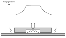
Air hockey is a game based on an aerostatic bearing which suspends the puck and player's paddles to provide low friction and thus fast motion. The bearing uses a flat plane with periodic orifices which deliver air just over ambient pressure. The puck and paddles rest on air.
Another example of a fluid bearing is ice skating. Ice skates form a hydrodynamic fluid bearing where the skate and ice are separated by a layer of water caused by entropy (formerly thought to be caused by pressure-induced melting; see ice skating for details.)
Michell/Kingsbury tilting-pad fluid bearings
Michell/Kingsbury fluid dynamic tilting-pad bearings were invented independently and almost simultaneously by both British-born Australian, Anthony George Maldon Michell and American tribologist Albert Kingsbury. Both designs were near-identical except for differences in the approach used for pivoting the pads. Michell mathematically derived the pressure distribution where a span-wise line pivot was placed, allowing the load to act through the point of maximum fluid pressure. The Kingsbury patent lacked this mathematical approach, and the pad's pivot point was placed in the geometric centre of the bearing.[5] Michell's patent (in England and Australia) was granted in 1905, while Kingsbury's first patent attempt was 1907. Kingsbury's U.S. patent was eventually granted in 1911 after he demonstrated that he had been working on the concept for many years. As stated by Sydney Walker, a long-time employee of Michell's, the granting of Kingsbury's patent was "a blow which Michell found hard to accept".
The bearing has sectional shoes, or pads on pivots. When the bearing is in operation, the rotating part of the bearing carries fresh oil in to the pad area through viscous drag. Fluid pressure causes the pad to tilt slightly, creating a narrow constriction between the shoe and the other bearing surface. A wedge of pressurised fluid builds behind this constriction, separating the moving parts. The tilt of the pad adaptively changes with bearing load and speed. Various design details ensure continued replenishment of the oil to avoid overheating and pad damage.
Michell/Kingsbury fluid bearings are used in a wider variety of heavy-duty rotating equipment, including in hydroelectric plants to support turbines and generators weighing hundreds of tons. They are also used in very heavy machinery, such as marine propeller shafts.
The first tilting pad bearing in service was probably built under A.G.M. Michell's guidance by George Weymoth (Pty) Ltd, for a centrifugal pump at Cohuna on the Murray River, Victoria, Australia, in 1907, just two years after Michell had published and patented his three-dimensional solution to Reynold's equation. By 1913, the great merits of the tilting-pad bearing had been recognised for marine applications. The first English ship to be fitted out with the bearing was the cross-channel steamboat the Paris, but many naval vessels were similarly equipped during the First World War. The practical results were spectacular – the troublesome thrust block became dramatically smaller and lighter, significantly more efficient, and remarkably free from maintenance troubles. It was estimated that the Royal Navy saved coal to a value of £500,000 in 1918 alone as a result of fitting Michell's tilting-pad bearings.
According to the ASME (see reference link), the first Michell/Kingsbury fluid bearing in the US was installed in the Holtwood Hydroelectric Power Plant (on the Susquehanna River, near Lancaster, Pennsylvania, US) in 1912. The 2.25-tonne bearing supports a water turbine and electric generator with a rotating mass of about 165 tonnes and water turbine pressure adding another 40 tonnes. The bearing has been in nearly continuous service since 1912, with no parts replaced. The ASME reported it was still in service as of 2000. As of 2002, the manufacturer estimated the bearings at Holtwood should have a maintenance-free life of about 1,300 years.
Software
There are bearing specific software packages capable of solving the fluid film system of equations and the governing lubrication (Reynolds) equations which define fluid film bearing operation. Many of the codes are proprietary to bearing manufacturers for design of that vendor’s products. Commercial software is available that handles cylindrical journals, thrust bearings, tilting-pad bearing, and conical bearings, all in either the hydrodynamic, hydrostatic, or hybrid mode of operation. These products make it easy to add bearing geometries such as plain sleeve, tapered land, elliptical bore, offset half, Rayleigh step, pressure dam, grooving, orifices, etc. Some utilize FEA solvers and have many years of development invested in their solution techniques, and can be used to predict minimum operating film-thickness, lubrication temperature rise and flow rate, load capacity, and power loss. These bearing specific codes can be used to design new bearings or analyze problematic bearings in order to improve the performance.
Fluid-film bearing design and analysis codes:
- ARMD BEARINGS (Rotor Bearing Technology & Software, Inc.) - Commercial FEA-based software for fluid-film bearings (hydrodynamic, hydrostatic, and hybrid) design, optimization, and performance evaluation, used worldwide by engineers at OEMs and end-users across all industries.
- Romac Industrial Research Program (ROMAC) is an industry consortium that maintains bearing codes for journal, thrust and tilting pad bearings.
References
- 1 2 3 4 Rowe, W. Brian (2012). Hydrostatic, Aerostatic and Hybrid Bearing Design. Butterworth-Heinemann. pp. 1–4. ISBN 0123972396.
- ↑ Girard, L. Dominique (1852). Hydraulique appliquée. Nouveau système de locomotion sur les chemins de fer (Applied hydraulics. New locomotion system for railways). Ecole Polytechnique.
- ↑ Il’ina T.E., Prodan N.V. (2015). "Element design for an inkjet system of hydrostatic gas bearing control.". Scientific and Technical Journal of Information Technologies, Mechanics and Optics. 15 (5): 921–929.
- ↑ Ghosal, Arindam. "A Review of Fluid Film Bearing" Bangladesh Society of Mechanical Engineers, 2010. Retrieved 2013-07-11.
- ↑ Stachowiak, Gwidon; Batchelor, Andrew W. "Engineering Tribology pp 135–136", Butterworth–Heinemann, London, 31 March 2011. Retrieved on 23 March 2013.
External links
- ASME History Brochure about Kingsbury's Susquehanna Bearing
- A 91-page 10.6MB NASA technical handbook Lubrication of Machine Elements, NASA-RP-1126 by B.J.Hamrock, 1984 here.
- Kinematic Models for Design Digital Library (KMODDL) – Movies and photos of hundreds of working mechanical-systems models at Cornell University. Also includes an e-book library of classic texts on mechanical design and engineering.
- – A technical discussion introducing air bearings and their many applications at Specialty Components Inc.
- – A video demonstration of a spherical air bearing.