Fuzzy control system
A fuzzy control system is a control system based on fuzzy logic—a mathematical system that analyzes analog input values in terms of logical variables that take on continuous values between 0 and 1, in contrast to classical or digital logic, which operates on discrete values of either 1 or 0 (true or false, respectively).[1][2]
Overview
Fuzzy logic is widely used in machine control. The term "fuzzy" refers to the fact that the logic involved can deal with concepts that cannot be expressed as the "true" or "false" but rather as "partially true". Although alternative approaches such as genetic algorithms and neural networks can perform just as well as fuzzy logic in many cases, fuzzy logic has the advantage that the solution to the problem can be cast in terms that human operators can understand, so that their experience can be used in the design of the controller. This makes it easier to mechanize tasks that are already successfully performed by humans.[1]
History and applications
Fuzzy logic was first proposed by Lotfi A. Zadeh of the University of California at Berkeley in a 1965 paper.[3] He elaborated on his ideas in a 1973 paper that introduced the concept of "linguistic variables", which in this article equates to a variable defined as a fuzzy set.[4] Other research followed, with the first industrial application, a cement kiln built in Denmark, coming on line in 1975.
Fuzzy systems were initially implemented in Japan.
- Interest in fuzzy systems was sparked by Seiji Yasunobu and Soji Miyamoto of Hitachi, who in 1985 provided simulations that demonstrated the feasibility of fuzzy control systems for the Sendai railway. Their ideas were adopted, and fuzzy systems were used to control accelerating, braking, and stopping when the line opened in 1987.
- In 1987, Takeshi Yamakawa demonstrated the use of fuzzy control, through a set of simple dedicated fuzzy logic chips, in an "inverted pendulum" experiment. This is a classic control problem, in which a vehicle tries to keep a pole mounted on its top by a hinge upright by moving back and forth. Yamakawa subsequently made the demonstration more sophisticated by mounting a wine glass containing water and even a live mouse to the top of the pendulum: the system maintained stability in both cases. Yamakawa eventually went on to organize his own fuzzy-systems research lab to help exploit his patents in the field.
- Japanese engineers subsequently developed a wide range of fuzzy systems for both industrial and consumer applications. In 1988 Japan established the Laboratory for International Fuzzy Engineering (LIFE), a cooperative arrangement between 48 companies to pursue fuzzy research. The automotive company Volkswagen was the only foreign corporate member of LIFE, dispatching a researcher for a duration of three years.
- Japanese consumer goods often incorporate fuzzy systems. Matsushita vacuum cleaners use microcontrollers running fuzzy algorithms to interrogate dust sensors and adjust suction power accordingly. Hitachi washing machines use fuzzy controllers to load-weight, fabric-mix, and dirt sensors and automatically set the wash cycle for the best use of power, water, and detergent.
- Canon developed an autofocusing camera that uses a charge-coupled device (CCD) to measure the clarity of the image in six regions of its field of view and use the information provided to determine if the image is in focus. It also tracks the rate of change of lens movement during focusing, and controls its speed to prevent overshoot. The camera's fuzzy control system uses 12 inputs: 6 to obtain the current clarity data provided by the CCD and 6 to measure the rate of change of lens movement. The output is the position of the lens. The fuzzy control system uses 13 rules and requires 1.1 kilobytes of memory.
- An industrial air conditioner designed by Mitsubishi uses 25 heating rules and 25 cooling rules. A temperature sensor provides input, with control outputs fed to an inverter, a compressor valve, and a fan motor. Compared to the previous design, the fuzzy controller heats and cools five times faster, reduces power consumption by 24%, increases temperature stability by a factor of two, and uses fewer sensors.
- Other applications investigated or implemented include: character and handwriting recognition; optical fuzzy systems; robots, including one for making Japanese flower arrangements; voice-controlled robot helicopters (hovering is a "balancing act" rather similar to the inverted pendulum problem); rehabilitation robotics to provide patient-specific solutions (e.g. to control heart rate and blood pressure [5]); control of flow of powders in film manufacture; elevator systems; and so on.
Work on fuzzy systems is also proceeding in the United State and Europe, although on a less extensive scale than in Japan.
- The US Environmental Protection Agency has investigated fuzzy control for energy-efficient motors, and NASA has studied fuzzy control for automated space docking: simulations show that a fuzzy control system can greatly reduce fuel consumption.
- Firms such as Boeing, General Motors, Allen-Bradley, Chrysler, Eaton, and Whirlpool have worked on fuzzy logic for use in low-power refrigerators, improved automotive transmissions, and energy-efficient electric motors.
- In 1995 Maytag introduced an "intelligent" dishwasher based on a fuzzy controller and a "one-stop sensing module" that combines a thermistor, for temperature measurement; a conductivity sensor, to measure detergent level from the ions present in the wash; a turbidity sensor that measures scattered and transmitted light to measure the soiling of the wash; and a magnetostrictive sensor to read spin rate. The system determines the optimum wash cycle for any load to obtain the best results with the least amount of energy, detergent, and water. It even adjusts for dried-on foods by tracking the last time the door was opened, and estimates the number of dishes by the number of times the door was opened.
Research and development is also continuing on fuzzy applications in software, as opposed to firmware, design, including fuzzy expert systems and integration of fuzzy logic with neural-network and so-called adaptive "genetic" software systems, with the ultimate goal of building "self-learning" fuzzy-control systems.[6] These systems can be employed to control complex, nonlinear dynamic plants, for example, human body.[5][6][7]
Fuzzy sets
The input variables in a fuzzy control system are in general mapped by sets of membership functions similar to this, known as "fuzzy sets". The process of converting a crisp input value to a fuzzy value is called "fuzzification".
A control system may also have various types of switch, or "ON-OFF", inputs along with its analog inputs, and such switch inputs of course will always have a truth value equal to either 1 or 0, but the scheme can deal with them as simplified fuzzy functions that happen to be either one value or another.
Given "mappings" of input variables into membership functions and truth values, the microcontroller then makes decisions for what action to take, based on a set of "rules", each of the form:
  IF brake temperature IS warm AND speed IS not very fast
  THEN brake pressure IS slightly decreased.
In this example, the two input variables are "brake temperature" and "speed" that have values defined as fuzzy sets. The output variable, "brake pressure" is also defined by a fuzzy set that can have values like "static" or "slightly increased" or "slightly decreased" etc.
This rule by itself is very puzzling since it looks like it could be used without bothering with fuzzy logic, but remember that the decision is based on a set of rules:
- All the rules that apply are invoked, using the membership functions and truth values obtained from the inputs, to determine the result of the rule.
- This result in turn will be mapped into a membership function and truth value controlling the output variable.
- These results are combined to give a specific ("crisp") answer, the actual brake pressure, a procedure known as "defuzzification".
This combination of fuzzy operations and rule-based "inference" describes a "fuzzy expert system".
Traditional control systems are based on mathematical models in which the control system is described using one or more differential equations that define the system response to its inputs. Such systems are often implemented as "PID controllers" (proportional-integral-derivative controllers). They are the products of decades of development and theoretical analysis, and are highly effective.
If PID and other traditional control systems are so well-developed, why bother with fuzzy control? It has some advantages. In many cases, the mathematical model of the control process may not exist, or may be too "expensive" in terms of computer processing power and memory, and a system based on empirical rules may be more effective.
Furthermore, fuzzy logic is well suited to low-cost implementations based on cheap sensors, low-resolution analog-to-digital converters, and 4-bit or 8-bit one-chip microcontroller chips. Such systems can be easily upgraded by adding new rules to improve performance or add new features. In many cases, fuzzy control can be used to improve existing traditional controller systems by adding an extra layer of intelligence to the current control method.
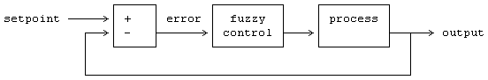
Fuzzy control in detail
Fuzzy controllers are very simple conceptually. They consist of an input stage, a processing stage, and an output stage. The input stage maps sensor or other inputs, such as switches, thumbwheels, and so on, to the appropriate membership functions and truth values. The processing stage invokes each appropriate rule and generates a result for each, then combines the results of the rules. Finally, the output stage converts the combined result back into a specific control output value.
The most common shape of membership functions is triangular, although trapezoidal and bell curves are also used, but the shape is generally less important than the number of curves and their placement. From three to seven curves are generally appropriate to cover the required range of an input value, or the "universe of discourse" in fuzzy jargon.
As discussed earlier, the processing stage is based on a collection of logic rules in the form of IF-THEN statements, where the IF part is called the "antecedent" and the THEN part is called the "consequent". Typical fuzzy control systems have dozens of rules.
Consider a rule for a thermostat:
IF (temperature is "cold") THEN (heater is "high")
This rule uses the truth value of the "temperature" input, which is some truth value of "cold", to generate a result in the fuzzy set for the "heater" output, which is some value of "high". This result is used with the results of other rules to finally generate the crisp composite output. Obviously, the greater the truth value of "cold", the higher the truth value of "high", though this does not necessarily mean that the output itself will be set to "high" since this is only one rule among many. In some cases, the membership functions can be modified by "hedges" that are equivalent to adverbs. Common hedges include "about", "near", "close to", "approximately", "very", "slightly", "too", "extremely", and "somewhat". These operations may have precise definitions, though the definitions can vary considerably between different implementations. "Very", for one example, squares membership functions; since the membership values are always less than 1, this narrows the membership function. "Extremely" cubes the values to give greater narrowing, while "somewhat" broadens the function by taking the square root.
In practice, the fuzzy rule sets usually have several antecedents that are combined using fuzzy operators, such as AND, OR, and NOT, though again the definitions tend to vary: AND, in one popular definition, simply uses the minimum weight of all the antecedents, while OR uses the maximum value. There is also a NOT operator that subtracts a membership function from 1 to give the "complementary" function.
There are several ways to define the result of a rule, but one of the most common and simplest is the "max-min" inference method, in which the output membership function is given the truth value generated by the premise.
Rules can be solved in parallel in hardware, or sequentially in software. The results of all the rules that have fired are "defuzzified" to a crisp value by one of several methods. There are dozens, in theory, each with various advantages or drawbacks.
The "centroid" method is very popular, in which the "center of mass" of the result provides the crisp value. Another approach is the "height" method, which takes the value of the biggest contributor. The centroid method favors the rule with the output of greatest area, while the height method obviously favors the rule with the greatest output value.
The diagram below demonstrates max-min inferencing and centroid defuzzification for a system with input variables "x", "y", and "z" and an output variable "n". Note that "mu" is standard fuzzy-logic nomenclature for "truth value":

Notice how each rule provides a result as a truth value of a particular membership function for the output variable. In centroid defuzzification the values are OR'd, that is, the maximum value is used and values are not added, and the results are then combined using a centroid calculation.
Fuzzy control system design is based on empirical methods, basically a methodical approach to trial-and-error. The general process is as follows:
- Document the system's operational specifications and inputs and outputs.
- Document the fuzzy sets for the inputs.
- Document the rule set.
- Determine the defuzzification method.
- Run through test suite to validate system, adjust details as required.
- Complete document and release to production.
As a general example, consider the design of a fuzzy controller for a steam turbine. The block diagram of this control system appears as follows:
The input and output variables map into the following fuzzy set:
 —where:
  N3:   Large negative.
  N2:   Medium negative.
  N1:   Small negative.
  Z:    Zero.
  P1:   Small positive.
  P2:   Medium positive.
  P3:   Large positive.
The rule set includes such rules as:
rule 1:  IF temperature IS cool AND pressure IS weak,
         THEN throttle is P3.
rule 2:  IF temperature IS cool AND pressure IS low,
         THEN throttle is P2.
rule 3:  IF temperature IS cool AND pressure IS ok,
         THEN throttle is Z.
rule 4:  IF temperature IS cool AND pressure IS strong,
         THEN throttle is N2.
In practice, the controller accepts the inputs and maps them into their membership functions and truth values. These mappings are then fed into the rules. If the rule specifies an AND relationship between the mappings of the two input variables, as the examples above do, the minimum of the two is used as the combined truth value; if an OR is specified, the maximum is used. The appropriate output state is selected and assigned a membership value at the truth level of the premise. The truth values are then defuzzified. For an example, assume the temperature is in the "cool" state, and the pressure is in the "low" and "ok" states. The pressure values ensure that only rules 2 and 3 fire:


The two outputs are then defuzzified through centroid defuzzification:
   __________________________________________________________________

                                       |          Z      P2
                                    1 -+          *       *
                                       |         * *     * *
                                       |        *   *   *   *
                                       |       *     * *     *
                                       |      *       222222222
                                       |     *       22222222222
                                       |    333333332222222222222
                                       +---33333333222222222222222-->
                                                        ^
                                                      +150
   __________________________________________________________________
The output value will adjust the throttle and then the control cycle will begin again to generate the next value .
Building a fuzzy controller
Consider implementing with a microcontroller chip a simple feedback controller:
A fuzzy set is defined for the input error variable "e", and the derived change in error, "delta", as well as the "output", as follows:
  LP:  large positive
  SP:  small positive
  ZE:  zero
  SN:  small negative
  LN:  large negative
If the error ranges from -1 to +1, with the analog-to-digital converter used having a resolution of 0.25, then the input variable's fuzzy set (which, in this case, also applies to the output variable) can be described very simply as a table, with the error / delta / output values in the top row and the truth values for each membership function arranged in rows beneath:
  _______________________________________________________________________

              -1    -0.75  -0.5   -0.25    0     0.25   0.5    0.75    1
  _______________________________________________________________________

   mu(LP)      0      0      0      0      0      0     0.3    0.7     1
   mu(SP)      0      0      0      0     0.3    0.7     1     0.7    0.3
   mu(ZE)      0      0     0.3    0.7     1     0.7    0.3     0      0
   mu(SN)     0.3    0.7     1     0.7    0.3     0      0      0      0
   mu(LN)      1     0.7    0.3     0      0      0      0      0      0
  _______________________________________________________________________—or, in graphical form (where each "X" has a value of 0.1):
         LN           SN           ZE           SP           LP
      +------------------------------------------------------------------+
      |                                                                  |
-1.0  |  XXXXXXXXXX   XXX          :            :            :           |
-0.75 |  XXXXXXX      XXXXXXX      :            :            :           |
-0.5  |  XXX          XXXXXXXXXX   XXX          :            :           |
-0.25 |  :            XXXXXXX      XXXXXXX      :            :           |
 0.0  |  :            XXX          XXXXXXXXXX   XXX          :           |
 0.25 |  :            :            XXXXXXX      XXXXXXX      :           |
 0.5  |  :            :            XXX          XXXXXXXXXX   XXX         |
 0.75 |  :            :            :            XXXXXXX      XXXXXXX     |
 1.0  |  :            :            :            XXX          XXXXXXXXXX  |
      |                                                                  |
      +------------------------------------------------------------------+
Suppose this fuzzy system has the following rule base:
  rule 1:  IF e = ZE AND delta = ZE THEN output = ZE
  rule 2:  IF e = ZE AND delta = SP THEN output = SN
  rule 3:  IF e = SN AND delta = SN THEN output = LP
  rule 4:  IF e = LP OR  delta = LP THEN output = LN
These rules are typical for control applications in that the antecedents consist of the logical combination of the error and error-delta signals, while the consequent is a control command output. The rule outputs can be defuzzified using a discrete centroid computation:
SUM( I = 1 TO 4 OF ( mu(I) * output(I) ) ) / SUM( I = 1 TO 4 OF mu(I) )
Now, suppose that at a given time we have:
  e     = 0.25
  delta = 0.5
Then this gives:
  ________________________

              e     delta
  ________________________

  mu(LP)      0      0.3
  mu(SP)     0.7      1
  mu(ZE)     0.7     0.3
  mu(SN)      0       0
  mu(LN)      0       0
  ________________________
Plugging this into rule 1 gives:
  rule 1:  IF e = ZE AND delta = ZE THEN output = ZE

     mu(1)     = MIN( 0.7, 0.3 ) = 0.3
     output(1) = 0
-- where:
- mu(1): Truth value of the result membership function for rule 1. In terms of a centroid calculation, this is the "mass" of this result for this discrete case.
- output(1): Value (for rule 1) where the result membership function (ZE) is maximum over the output variable fuzzy set range. That is, in terms of a centroid calculation, the location of the "center of mass" for this individual result. This value is independent of the value of "mu". It simply identifies the location of ZE along the output range.
The other rules give:
  rule 2:  IF e = ZE AND delta = SP THEN output = SN

     mu(2)     = MIN( 0.7, 1 ) = 0.7
     output(2) = -0.5
  rule 3: IF e = SN AND delta = SN THEN output = LP

     mu(3)     = MIN( 0.0, 0.0 ) = 0
     output(3) = 1
  rule 4: IF e = LP OR  delta = LP THEN output = LN

     mu(4)     = MAX( 0.0, 0.3 ) = 0.3
     output(4) = -1
The centroid computation yields:
—for the final control output. Simple. Of course the hard part is figuring out what rules actually work correctly in practice.


If you have problems figuring out the centroid equation, remember that a centroid is defined by summing all the moments (location times mass) around the center of gravity and equating the sum to zero. So if is the center of gravity, is the location of each mass, and is each mass, this gives:


In our example, the values of mu correspond to the masses, and the values of X to location of the masses (mu, however, only 'corresponds to the masses' if the initial 'mass' of the output functions are all the same/equivalent. If they are not the same, i.e. some are narrow triangles, while others maybe wide trapizoids or shouldered triangles, then the mass or area of the output function must be known or calculated. It is this mass that is then scaled by mu and multiplied by its location X_i).
This system can be implemented on a standard microprocessor, but dedicated fuzzy chips are now available. For example, Adaptive Logic INC of San Jose, California, sells a "fuzzy chip", the AL220, that can accept four analog inputs and generate four analog outputs. A block diagram of the chip is shown below:
              +---------+                              +-------+
 analog --4-->| analog  |                              | mux / +--4--> analog
   in         |   mux   |                              |  SH   |        out
              +----+----+                              +-------+
                   |                                       ^
                   V                                       |
            +-------------+                             +--+--+
            | ADC / latch |                             | DAC |
            +------+------+                             +-----+
                   |                                       ^
                   |                                       |
                   8         +-----------------------------+
                   |         |                             |
                   |         V                             |
                   |   +-----------+      +-------------+  |
                   +-->| fuzzifier |      | defuzzifier +--+
                       +-----+-----+      +-------------+
                             |                   ^
                             |  +-------------+  |
                             |  |    rule     |  |
                             +->|  processor  +--+
                                | (50 rules)  |
                                +------+------+
                                       |
                                +------+------+
                                |  parameter  |
                                |    memory   |
                                |   256 x 8   |
                                +-------------+

    ADC:  analog-to-digital converter
    DAC:  digital-to-analog converter
    SH:   sample/hold
Antilock brakes
As a first example, consider an anti-lock braking system, directed by a microcontroller chip. The microcontroller has to make decisions based on brake temperature, speed, and other variables in the system.
The variable "temperature" in this system can be subdivided into a range of "states": "cold", "cool", "moderate", "warm", "hot", "very hot". The transition from one state to the next is hard to define.
An arbitrary static threshold might be set to divide "warm" from "hot". For example, at exactly 90 degrees, warm ends and hot begins. But this would result in a discontinuous change when the input value passed over that threshold. The transition wouldn't be smooth, as would be required in braking situations.
The way around this is to make the states fuzzy. That is, allow them to change gradually from one state to the next. In order to do this there must be a dynamic relationship established between different factors.
We start by defining the input temperature states using "membership functions":

With this scheme, the input variable's state no longer jumps abruptly from one state to the next. Instead, as the temperature changes, it loses value in one membership function while gaining value in the next. In other words, its ranking in the category of cold decreases as it becomes more highly ranked in the warmer category.
At any sampled timeframe, the "truth value" of the brake temperature will almost always be in some degree part of two membership functions: i.e.: '0.6 nominal and 0.4 warm', or '0.7 nominal and 0.3 cool', and so on.
The above example demonstrates a simple application, using the abstraction of values from multiple values. This only represents one kind of data, however, in this case, temperature.
Adding additional sophistication to this braking system, could be done by additional factors such as traction, speed, inertia, set up in dynamic functions, according to the designed fuzzy system.[8]
Logical interpretation of fuzzy control
In spite of the appearance there are several difficulties to give a rigorous logical interpretation of the IF-THEN rules. As an example, interpret a rule as IF (temperature is "cold") THEN (heater is "high") by the first order formula Cold(x)→High(y) and assume that r is an input such that Cold(r) is false. Then the formula Cold(r)→High(t) is true for any t and therefore any t gives a correct control given r. A rigorous logical justification of fuzzy control is given in Hájek's book (see Chapter 7) where fuzzy control is represented as a theory of Hájek's basic logic.[2] Also in Gerla 2005 [9] another logical approach to fuzzy control is proposed based on fuzzy logic programming.Indeed, denote by f the fuzzy function arising of an IF-THEN systems of rules. Then we can translate this system into a fuzzy program P containing a series of rules whose head is "Good(x,y)". The interpretation of this predicate in the least fuzzy Herbrand model of P coincides with f. This gives further useful tools to fuzzy control.
See also
- Dynamic logic
- Bayesian inference
- Function approximation
- Fuzzy markup language
- Hysteresis
- Neural networks
- Neuro-fuzzy
- Fuzzy control language
- Type-2 fuzzy sets and systems
References
- 1 2 Pedrycz, Witold (1993). Fuzzy control and fuzzy systems (2 ed.). Research Studies Press Ltd.
- 1 2 Hájek, Petr (1998). Metamathematics of fuzzy logic (4 ed.). Springer Science & Business Media.
- ↑ Zadeh, Lotfi A. (1965). "Fuzzy sets". Information and Control. 8 (3): 338–353. doi:10.1016/S0019-9958(65)90241-X.
- ↑ Zadeh, Lotfi A. (1973). "Outline of a new approach to the analysis of complex systems and decision processes". IEEE Transactions on Systems, Man and Cybernetics. 1: 28–44. doi:10.1109/TSMC.1973.5408575.
- 1 2 Sarabadani Tafreshi, Amirehsan; Klamroth-Marganska, V.; Nussbaumer, S.; Riener, R. (2015). "Real-time closed-loop control of human heart rate and blood pressure". IEEE Transactions on Biomedical Engineering. 62 (5): 1434–1442. doi:10.1109/TBME.2015.2391234. PMID 25594957.
- 1 2 Mamdani, Ebrahim H (1974). "Application of fuzzy algorithms for control of simple dynamic plant". Proceedings of the Institution of Electrical Engineers. 121 (12): 1585–1588. doi:10.1049/piee.1974.0328.
- ↑ Bastian, Andreas (2000). "Identifying fuzzy models utilizing genetic programming". Fuzzy sets and systems. 113 (3): 333–350. doi:10.1016/S0165-0114(98)00086-4.
- ↑ Vichuzhanin, Vladimir (12 April 2012). "Realization of a fuzzy controller with fuzzy dynamic correction". Central European Journal of Engineering. 2 (3): 392–398. doi:10.2478/s13531-012-0003-7.
- ↑ Gerla, Giangiacomo (2005). "Fuzzy logic programming and fuzzy control". Studia Logica. 79 (2): 231–254. doi:10.1007/s11225-005-2977-0.
Further reading
- Kevin M. Passino and Stephen Yurkovich, Fuzzy Control, Addison Wesley Longman, Menlo Park, CA, 1998 (522 pages)
- Kazuo Tanaka; Hua O. Wang (2001). Fuzzy control systems design and analysis: a linear matrix inequality approach. John Wiley and Sons. ISBN 978-0-471-32324-2.
- Cox, E. (Oct. 1992). Fuzzy fundamentals. Spectrum, IEEE, 29:10. pp. 58–61.
- Cox, E. (Feb. 1993) Adaptive fuzzy systems. Spectrum, IEEE, 30:2. pp. 7–31.
- Jan Jantzen, "Tuning Of Fuzzy PID Controllers", Technical University of Denmark, report 98-H 871, September 30, 1998.
- Jan Jantzen, Foundations of Fuzzy Control. Wiley, 2007 (209 pages) (Table of contents)
- Computational Intelligence: A Methodological Introduction by Kruse, Borgelt, Klawonn, Moewes, Steinbrecher, Held, 2013, Springer, ISBN 9781447150121
External links
- Introduction to Fuzzy Control
- Fuzzy Logic in Embedded Microcomputers and Control Systems
- IEC 1131-7 CD1 IEC 1131-7 CD1 PDF
- Online interactive demonstration of a system with 3 fuzzy rules