Halbach array

.png)
.png)
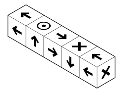
A Halbach array is a special arrangement of permanent magnets that augments the magnetic field on one side of the array while cancelling the field to near zero on the other side.[1] This is achieved by having a spatially rotating pattern of magnetisation.
The rotating pattern of permanent magnets (on the front face; on the left, up, right, down) can be continued indefinitely and have the same effect. The effect of this arrangement is roughly similar to many horseshoe magnets placed adjacent to each other, with similar poles touching.
The effect was discovered by John C. Mallinson in 1973, and these "one-sided flux" structures were initially described by him as a "curiosity", although he recognised at the time the potential for significant improvements in magnetic tape technology.[2]
In the 1980s, Lawrence Berkeley National Laboratory physicist Klaus Halbach independently invented the Halbach array to focus particle accelerator beams.[3]
Flat Halbach arrays
Magnetization
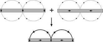
Although this magnetic flux distribution seems somewhat counter-intuitive to those familiar with, for example, bar magnets or solenoids, the reason for this flux distribution can be intuitively visualised using Mallinson's original diagram (note this uses the negative y-component, unlike the diagram in Mallinson's paper). The diagram shows the field from a strip of ferromagnetic material with alternating magnetization in the y direction (top left) and in the x direction (top right). Note that the field above the plane is in the same direction for both structures, but the field below the plane is in opposite directions. The effect of superimposing both of these structures is shown in the figure:
The crucial point is that the flux will cancel below the plane and reinforce itself above the plane. In fact, any magnetization pattern where the components of magnetization are out of phase with each other will result in a one-sided flux. The mathematical transform which shifts the phase of all components of some function by is called a Hilbert transform; the components of the magnetization vector can therefore be any Hilbert transform pair (the simplest of which is simply , as shown in the diagram above).


The field on the non-cancelling side of the ideal, continuously varying, infinite array is of the form:[4]

Where:
- is the field in the form


- is the magnitude of the field at the surface of the array

- is the spatial wavenumber, (i.e., the spatial frequency)


Applications
The advantages of one sided flux distributions are twofold:
- The field is twice as large on the side on which the flux is confined (in the idealized case).
- No stray field is produced (in the ideal case) on the opposite side. This helps with field confinement, usually a problem in the design of magnetic structures.
Although one-sided flux distributions may seem somewhat abstract, they have a surprising number of applications ranging from the refrigerator magnet through industrial applications such as the brushless AC motor and magnetic coupling, efficient voice coils,[5] magnetic drug targeting [6] to high-tech applications such as wiggler magnets used in particle accelerators and free electron lasers. This device is also a key component of the Inductrack Maglev train and rocket launch system [7] wherein the Halbach arrays repel loops of wire that form the track after the train has been accelerated to speed, lifting the train.
The simplest example of a one sided flux magnet is a refrigerator magnet. These are usually composed of powdered ferrite in a binder such as plastic or rubber. The extruded magnet is exposed to a rotating field giving the ferrite particles in the magnetic compound a magnetization resulting in a one-sided flux distribution. This distribution increases the holding force of the magnet when placed on a permeable surface, compared to the holding force from, say, a uniform magnetization of the magnetic compound.

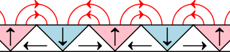
Scaling up this design and adding a top sheet gives a wiggler magnet, used in synchrotrons and free electron lasers. Wiggler magnets wiggle or oscillate an electron beam perpendicular to the magnetic field. As the electrons are undergoing acceleration they radiate electromagnetic energy in their flight direction, and as they interact with the light already emitted, photons along its line are emitted in phase, resulting in a "laser-like" monochromatic and coherent beam.
The design shown above is usually known as a Halbach wiggler. The magnetization vectors in the magnetized sheets rotate in the opposite senses to each other; above, the top sheet's magnetization vector rotates clockwise and the bottom sheet's magnetization vector rotates counter-clockwise. This design is chosen so that the x-components of the magnetic fields from the sheets cancel and the y-components reinforce so that the field is given by

where k is the wavenumber of the magnetic sheet given by the spacing between magnetic blocks with the same magnetization vector.
Variable flat arrays
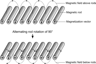

A series of magnetic rods, magnetized perpendicular to their axes, can be arranged into a Halbach array. If each rod is then rotated alternately through 90° the resultant field moves from one side of plane of the rods to the other, as shown schematically in the figure.
This arrangement allows the field to effectively be turned on and off above or below the plane of the rods, depending on the rotation of the rods. Such a device makes an efficient mechanical magnetic latch requiring no power. A detailed study of this arrangement has shown that each rod is subject to a strong torque from its neighboring rods, and therefore requires mechanical stabilization.[8] However, a simple and efficient solution, providing both stabilization and the ability to rotate each rod alternately, is simply to provide an equal gearing arrangement on each rod, as shown in the figure.
Halbach cylinder


A Halbach cylinder is a magnetized cylinder composed of ferromagnetic material producing (in the idealized case) an intense magnetic field confined entirely within the cylinder with zero field outside. The cylinders can also be magnetized such that the magnetic field is entirely outside the cylinder, with zero field inside. Several magnetization distributions are shown:
The direction of magnetization within the ferromagnetic material, in plane perpendicular to the axis of the cylinder, is given by
![M = M_r\left[\cos((k-1)(\phi-\pi/2))\hat{\rho}+\sin((k-1)(\phi-\pi/2))\hat{\phi}\right]](../I/m/de441bbd0c2f47ddd7ccd269d21295a65e2f1859.svg)
where Mr is the ferromagnetic remanence (A/m). A positive value of k-1 gives an internal magnetic field and a negative one gives an external magnetic field.
Ideally, these structures would be created from an infinite length cylinder of magnetic material with the direction of magnetization continuously varying. The magnetic flux produced by this ideal design would be perfectly uniform and be entirely confined to either the bore of the cylinder or the outside of the cylinder. Of course, the ideal case of infinite length is not realizable and in practice the finite length of the cylinders produces end effects which introduce non-uniformities in the field.[9][10] The difficulty of manufacturing a cylinder with a continuously varying magnetization also usually leads to the design being broken into segments.
Applications
These cylindrical structures are used in devices such as brushless AC motors, magnetic couplings and high field cylinders. Both brushless motors and coupling devices use multipole field arrangements:
- Brushless motors typically use cylindrical designs in which all the flux is confined to the centre of the bore (such as k = 4 above, a six pole rotor) with the AC coils also contained within the bore. Such self-shielding motors designs are more efficient and produce higher torque than conventional motor designs.
- Magnetic coupling devices transmit torque through magnetically transparent barriers (that is, the barrier is non-magnetic or is magnetic but is not affected by an applied magnetic field), for instance between sealed containers or pressurised vessels. The optimal torque couplings consists of a pair of coaxially nested cylinders with opposite +k and -k flux magnetization patterns, as this configuration is the only system for infinitely long cylinders that produce a torque.[11] In the lowest energy state, the outer flux of the inner cylinder exactly matches the internal flux of the outer cylinder. Rotating one cylinder relative to the other from this state results in a restoring torque.
Uniform fields
For the special case of k = 2, the field inside the bore is uniform, and is given by:

where the inner and outer cylinder radii are Ri and Ro, respectively. H is in the y direction. This is the simplest form of the Halbach cylinder, and it can be seen that if the ratio of outer to inner radii is greater than e the flux inside the bore actually exceeds the remanence of the magnetic material used to create the cylinder. However, care has to be taken not to produce a field that exceed the coercivity of the permanent magnets used, as this can result in "self-magnetocide" of the cylinder and the production of a much lower field than intended.[12][13]

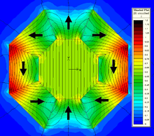
This cylindrical design is only one class of design which produces a uniform field inside a cavity within an array of permanent magnets. Other classes of design include wedge designs, proposed by Abele and Jensen in which wedges of magnetized material are arranged to provide uniform field within cavities inside the design as shown.
The direction of magnetization of the wedges in (A) can be calculated using a set of rules given by Abele, and allows for great freedom in the shape of the cavity. Another class of design is the magnetic mangle (B), proposed by Coey and Cugat,[14][15] in which uniformly magnetized rods are arranged such that their magnetization matches that of a Halbach cylinder, as shown for a six rod design. This design greatly increases access to the region of uniform field, at the expense of the volume of uniform field being smaller than in the cylindrical designs (although this area can be made larger by increasing the number of component rods). Rotating the rods relative to each other results in many possibilities including a dynamically variable field and various dipolar configurations. It can be seen that the designs shown in A and B are closely related to the k = 2 Halbach cylinder. Other very simple designs for a uniform field include separated magnets with soft iron return paths, as shown in figure (C).
In the last years, these Halbach dipoles have been used to conduct low-field NMR experiments.[16] Compared to commercially available (Bruker Minispec) standard plate geometries (C) of permanent magnets, they, as explained above, offer a huge bore diameter, while still having a reasonably homogeneous field.
Varying the field
Halbach cylinders give a static field. However cylinders can be nested, and by rotating one cylinder relative to the other, cancellation of the field and adjustment of the direction can be achieved.[17] As the outside field of a cylinder is quite low, the relative rotation does not require strong forces. In the ideal case of infinitely long cylinders there no force would be required to rotate a cylinder with respect to the other.
Halbach spheres
If the two dimensional magnetic distribution patterns of the Halbach cylinder are extended to three dimensions, the result is the Halbach sphere. These designs have an extremely uniform field within the interior of the design, as they are not affected by the 'end effects' prevalent in the finite length cylinder design. The magnitude of the uniform field for a sphere also increases to 4/3 the amount for the ideal cylindrical design with the same inner and outer radii. However, being spherical, access to the region of uniform field is usually restricted to a narrow hole at the top and bottom of the design.
The equation for the field in a Halbach sphere is:[18]

Higher fields are possible by optimising the spherical design to take account of the fact that it is composed of point dipoles (and not line dipoles). This results in the stretching of the sphere to an elliptical shape and having a non-uniform distribution of magnetization over the component parts of the sphere. Using this method, as well as soft pole pieces within the design, 4.5 T in a working volume of 20 mm3 was achieved by Bloch et al. in 1998[19] and this was increased further to 5 T in 2002,[20] although over a smaller working volume of 0.05 mm3. As hard materials are temperature dependent, refrigeration of the entire magnet array can increase the field within the working area further as shown by Kumada et al. This group also reported development of a 5.16 T Halbach dipole cylinder in 2003.[21]
See also
- Supermagnet
- Permanent magnet
- Strong focusing
- Inductrack uses Halbach arrays to generate strong fields for maglev
- Helmholtz coil can give very even magnetic fields
References
- ↑ Klaus Halbach (1980). "Design of permanent multipole magnets with oriented rare earth cobalt material" (PDF). Nuclear Instruments and Methods. 169 (1): 1–10. Bibcode:1980NucIM.169....1H. doi:10.1016/0029-554X(80)90094-4. ISSN 0029-554X.
- ↑ J.C. Mallinson, "One-Sided Fluxes — A Magnetic Curiosity?", IEEE Transactions on Magnetics, 9, 678-682, 1973, doi:10.1109/TMAG.1973.1067714
- ↑ "Magnetically levitated train takes flight"
- ↑
- ↑ http://www.google.com/patents/US7368838
- ↑ A. Sarwar; A. Nemirovski; B. Shapiro (2012). "Optimal Halbach permanent magnet designs for maximally pulling and pushing nanoparticles" (PDF). Journal of Magnetism and Magnetic Materials. 324 (5): 742–754. Bibcode:2012JMMM..324..742S. doi:10.1016/j.jmmm.2011.09.008.
- ↑ L. S. Tung; R. F. Post; J. Martinez-Frias (27 June 2001). "Final progress report for the NASA Inductrack model rocket launcher at the Lawrence Livermore National Laboratory" (PDF). UCRL-ID-144455.
- ↑ J. E. Hilton; S. M. McMurry (2012). "An adjustable linear Halbach array". Journal of Magnetism and Magnetic Materials. 324 (13): 2051–2056. Bibcode:2012JMMM..324.2051H. doi:10.1016/j.jmmm.2012.02.014.
- ↑ T. R. Ni Mhiochain; D. Weaire; S. M. McMurry; J. M. D. Coey (1999). "Analysis of torque in nested magnetic cylinders". Journal of Applied Physics. 86: 6412. doi:10.1063/1.371705.
- ↑ R. Bjørk (2011). "The ideal dimensions of a Halbach cylinder of finite length". Journal of Applied Physics. 109: 013915. arXiv:1410.0496
 . doi:10.1063/1.3525646.
 - ↑ R. Bjørk; A. Smith; C. R. H. Bahl (2010). "Analysis of the magnetic field, force, and torque for two-dimensional Halbach cylinders" (PDF). Journal of Magnetism and Magnetic Materials. 322: 133–141. doi:10.1016/j.jmmm.2009.08.044.
- ↑ R. Bjørk; A. Smith; C. R. H. Bahl (2015). "The efficiency and the demagnetization field of a general Halbach cylinder" (PDF). Journal of Magnetism and Magnetic Materials. 384: 128–132. doi:10.1016/j.jmmm.2015.02.034.
- ↑ A. R. Insinga; C. R. H. Bahl; R. Bjørk; A. Smith (2016). "Performance of Halbach magnet arrays with finite coercivity". Journal of Magnetism and Magnetic Materials. 407: 369–376. doi:10.1016/j.jmmm.2016.01.076.
- ↑ J. M. D. Coey; T.R. Ní Mhíocháin (2003). "Permanent Magnets". In F. Herlach; N. Miura. High Magnetic Fields: Science and Technology. Volume 1. World Scientific Publishing. pp. 25–47. ISBN 981-02-4964-0.
- ↑ O. Cugat; F. Bloch; J.C. Toussaint (1998). "4-Tesla Permanent Magnetic Flux Source". Proc. 15th International Workshop on Rare Earth Magnets and Their Applications: 807.
- ↑ Raich, H., Blümler, P., Design and construction of a dipolar Halbach array with a homogeneous field from identical bar magnets: NMR Mandhalas in Concepts in Magnetic Resonance Part B-Magnetic Resonance Engineering 01/2004; 23B:16-25
- ↑ Tip Magazine: Magnets, Markets, and Magic Cylinders The Industrial Physicist by Michael Coey and Denis Weaire
- ↑ Permanent magnet based sources of magnetic field
- ↑ Bloch, F. and Cugat, O. and Meunier, G. and Toussaint, J.C. (1998). "Innovating approaches to the generation of intense magnetic fields: design and optimization of a 4 Tesla permanent magnet flux source". IEEE Transactions on Magnetics. 34 (5): 2465–2468. Bibcode:1998ITM....34.2465B. doi:10.1109/20.717567.
- ↑
- ↑ Kumada, M. and Antokhin, E.I. and Iwashita, Y. and Aoki, M. and Sugiyama, E. (2004). "Super Strong Permanent Magnet Quadrupole for a Linear Collider" (PDF). IEEE Transactions on Applied Superconductivity. 14 (2): 1287–1289. doi:10.1109/TASC.2004.830555.
External links
- Passive levitation of a shaft
- Electric model aircraft motor
- magnet levitated vehicle switching system